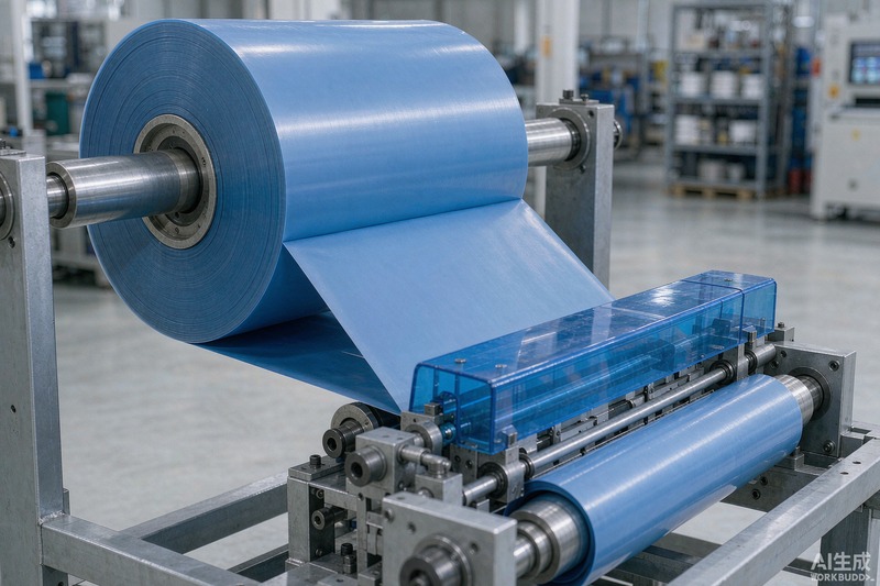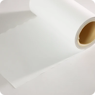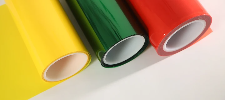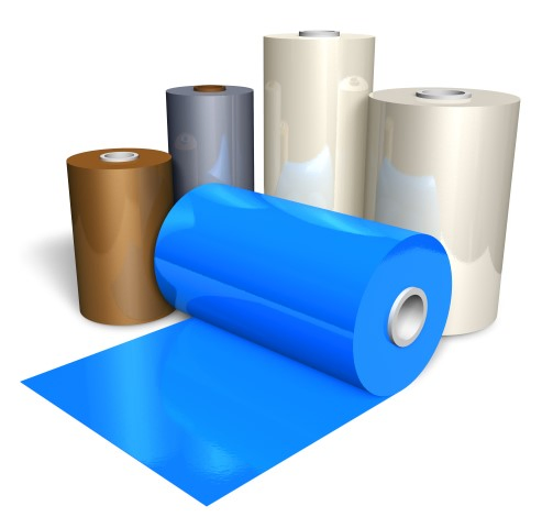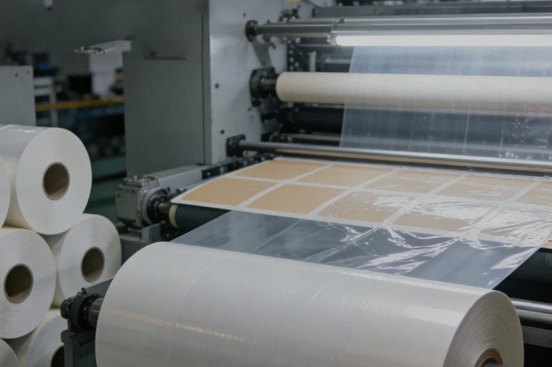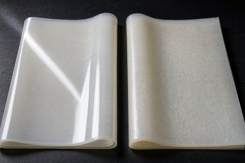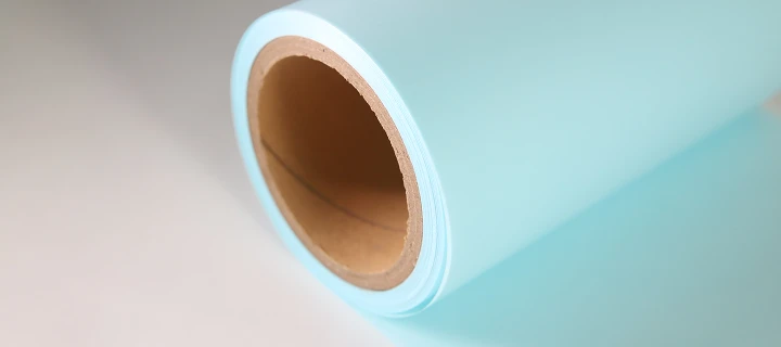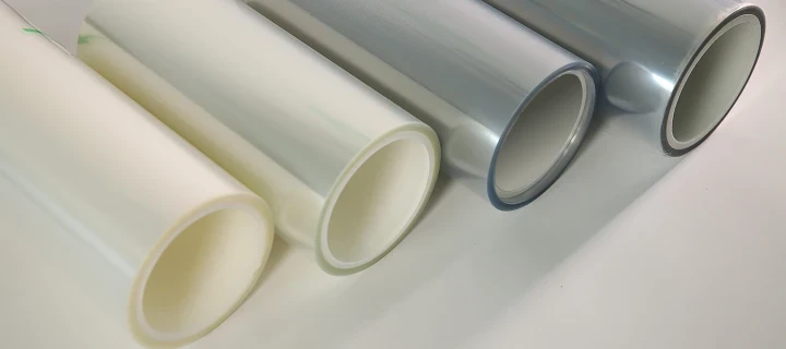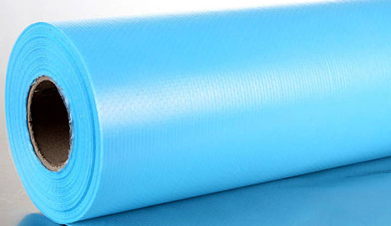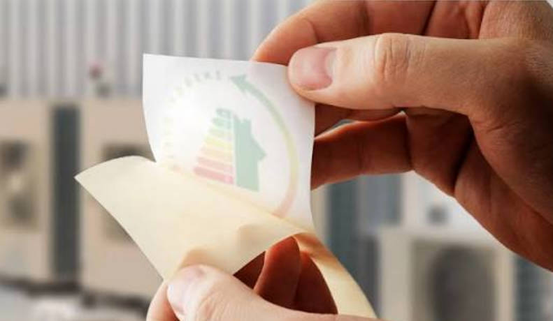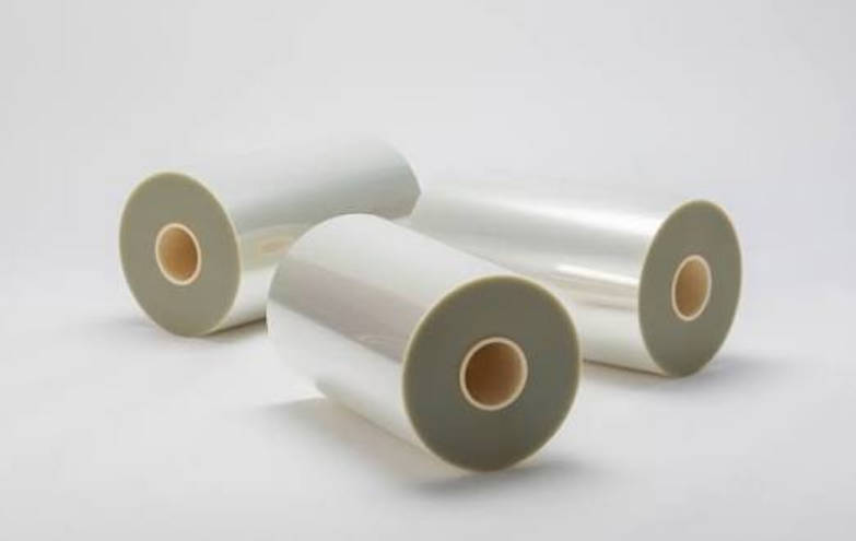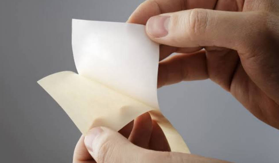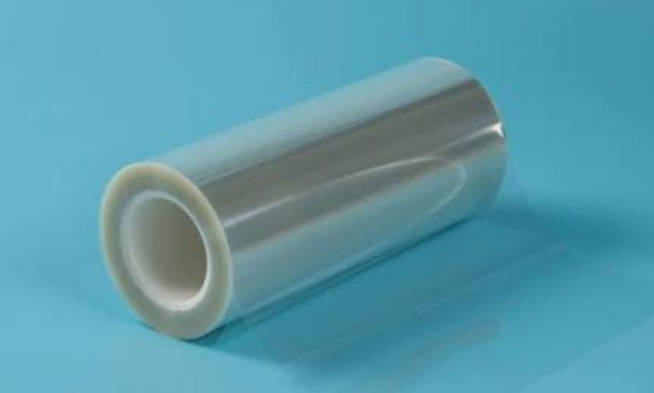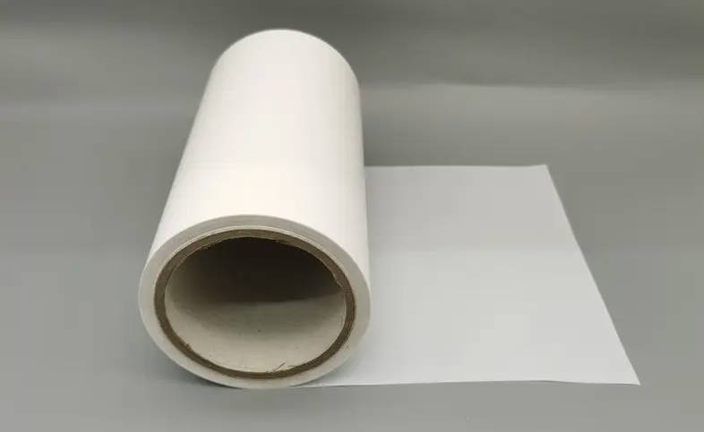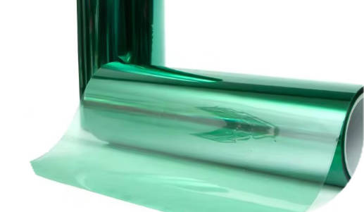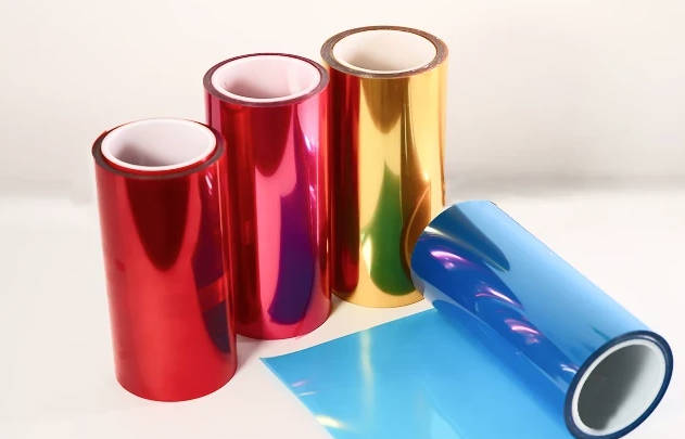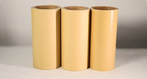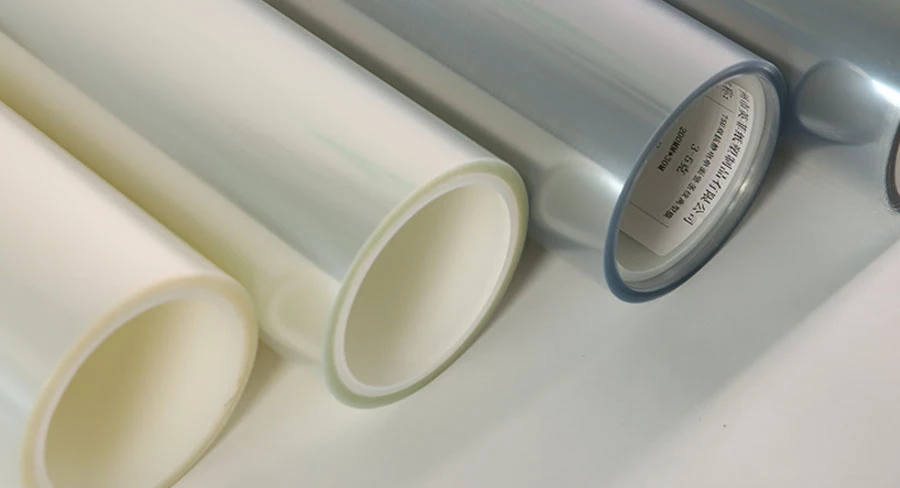
PET release film is an engineered polyethylene terephthalate substrate coated with a specialized anti-adhesion agent designed to carry, protect, and cleanly release pressure-sensitive adhesives, cast resins, and precision electronic components. Selecting the proper film requires balancing three technical variables: the chemical compatibility between the release coating and the adhesive matrix, the mechanical stability of the polyester carrier under converting tension, and the stability of the release force throughout thermal processing and storage.
This guide details the structural characteristics, coating chemistries, critical performance properties, and downstream processing conditions of polyester release liners, providing a practical framework to evaluate specifications and prevent converting defects.
What Is PET Release Film? Core Structure and Manufacturing Overview
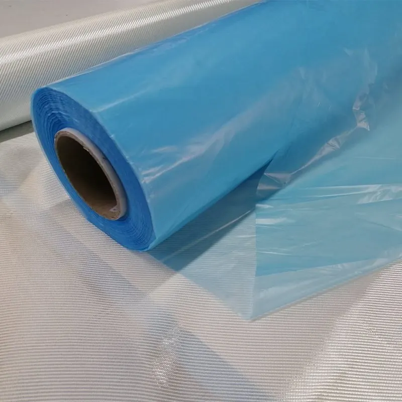
A PET release film functions as a temporary process carrier or protective backing. Unlike general-purpose plastic sheeting, it is engineered to deliver predictable release force values, high surface smoothness, and dimensional stability under tensile load and elevated curing temperatures.
Anatomy of a Release Liner: PET Base Film vs. Release Coating
The performance of the liner relies on the interface between two discrete components:
- The Biaxially Oriented Polyethylene Terephthalate (BOPET) Base: Manufactured via two-stage stretch orientation, BOPET provides high tensile modulus, low thermal shrinkage, optical clarity, and uniform caliper. It resists stretching during rotary die-cutting and web converting, maintaining registered tolerances across web handling lines.
- The Surface Treatment and Release Coating: A sub-micron chemical layer cured onto the PET substrate. In demanding converting lines, an in-line corona treatment or chemical priming step is applied before coating to ensure that the release agent bonds irreversibly to the base film, preventing coating transfer during subsequent peeling.
Substrate Comparison: PET vs. Paper vs. Polyolefin Films
Choosing the correct liner base depends on tensile demand, die-cutting mechanisms, moisture exposure, and surface roughness limits.
- PET Base Film: Delivers high tensile modulus, exceptional caliper uniformity, and minimal surface texture. It does not absorb moisture, making it dimensionally stable in humid environments. It serves as the benchmark substrate for precision electronic die-cutting, cast tape production, and high-speed rotary converting.
- Paper Liners (Glassine, CCK, PCK): Highly economical and heat-resistant, but susceptible to moisture absorption, dimensional variance, and fiber tear under sharp blade impacts. Paper surfaces exhibit higher micro-roughness, transferring micro-textures onto applied adhesive coatings.
- Polyolefin Films (PE, PP): Highly flexible with high elongation at break, but low tensile modulus and limited thermal resistance. Unsuitable for tension-sensitive, high-speed slitting or elevated-temperature curing lines.
Types of PET Release Films: Coating Chemistries and Configurations
Release characteristics are governed primarily by the chemical interaction between the release coating and the adhesive polymer.
Silicone Coating Chemistries
Polydimethylsiloxane (PDMS) networks constitute the most common release chemistry. They offer low surface energy and stable release across variable peeling speeds.
- Thermal-Cured Solvent Systems: Provide wide latitude in coating weight, uniform release force, and tight tolerances across heavy and ultra-light release ranges. Requires thermal evaporation tunnels to remove solvent carriers.
- Thermal-Cured Solventless Systems: A 100% solids chemical system cross-linked via platinum catalysis. Highly cost-effective and environmentally friendly, delivering consistent, reliable release force suitable for standard tape and label converting.
- UV-Cured Systems: Cured via photo-initiators under ultraviolet light. Eliminates high thermal exposure during curing, which helps prevent thermal shrinkage in thinner PET base gauges.
Fluorosilicone vs. Non-Silicone Systems
- Fluorosilicone liners: Standard silicone release agents fail when laminated to silicone-based adhesives, fusing together due to chemical affinity. Fluorosilicone formulations incorporate fluorinated side groups that resist wetting and bonding by silicone adhesives. They are the established carrier standard for silicone pressure-sensitive tapes and silicone thermal interface pads.
- Non-silicone coatings (Fluorine polymers, Alkyds, Polyolefins): Engineered for processes where trace silicone transfer presents contamination risks. Non-silicone formulations are preferred in high-vacuum electronics processing, automotive paint shop applications, and optical manufacturing where silicone volatiles could cause electrical contact failures or coating pinholes.
Structural Configurations: Single-Sided, Double-Sided, and Differential Release
- Single-Sided: Coated on one face; the reverse PET surface remains untreated or receives an anti-static treatment. Standard for single-coated adhesive tapes, graphic films, and component carriers.
- Double-Sided (Equal Release): Both faces are coated to achieve identical release force. Used primarily in transfer adhesive systems without an internal carrier web.
- Differential release levels: Features distinct release levels on opposite sides (e.g., easy release on Side A, tight release on Side B). This differential force ensures that an adhesive tape unwinds consistently on converting lines, allowing one side to peel freely during liner stripping without dislodging the opposite bond.
Critical Properties and Specifications: What Technical Data Matters?
Industrial specification sheets contain quantitative values that determine whether a liner will run reliably through slitting, punching, and laminating equipment.
| Parameter | Unit | Test Method Standard | Technical Significance |
| Release Force | g/25mm (or N/25mm) | FINAT FTM 1 / FTM 3, ASTM D3330 | Quantifies the peeling force needed to separate the liner from the adhesive at a defined angle and peel speed. |
| Residual Adhesion Rate | % | FINAT FTM 11 | Measures the percentage of adhesive strength retained after contact with the release liner, indicating the degree of silicone cross-linking. |
| Thermal Shrinkage | % | 150°C for 30 min (MD / TD) | Determines dimensional distortion, curl, and register drift during thermal drying, curing, or baking tunnels. |
| Surface Resistivity (ESD) | $\Omega/\text{sq}$ | ASTM D257 | Indicates static dissipation efficiency to avoid dust attraction, web cling, and electrostatic discharge damage. |
| Substrate Thickness | $\mu\text{m}$ (Gauge) | ISO 4593 / ASTM D6988 | Dictates tensile rigidity, blade penetration depth control, and burst strength during rotary converting. |
Understanding Release Force Classifications
Release forces are categorized based on standardized 180° peel testing at specific peel rates:
- Ultra-Light Release (1 to 5 g/25mm): Selected for high-speed automated label application, fragile web handling, and large-format lamination where high peel tension would stretch or tear thin functional substrates.
- Light Release (5 to 15 g/25mm): The baseline standard for graphic transfer tapes, foam lamination, and precision component die-cutting.
- Medium Release (15 to 40 g/25mm): Used where the liner must remain securely anchored to the adhesive layer during slitting and transport, yet peel away smoothly during manual or automated assembly.
- Heavy/Tight Release (40 to 100+ g/25mm): Applied to the tight side of differential transfer tapes, or as a protective backing for rough-textured, aggressive adhesives to prevent premature uncoupling during spooling.
Residual Adhesion Strength and Silicone Migration
A properly cross-linked coating locks all silicone polymer chains into an insoluble matrix. If the curing system is under-catalyzed or insufficiently heated, unreacted silicone monomers remain free within the coating layer.
When laminated to an adhesive, these free monomers migrate across the interface into the adhesive mass. Upon final application, the adhesive’s bonding performance drops significantly. High-grade industrial release films maintain a residual adhesion rate above 90%, confirming that minimal free silicone has migrated.
Key Industrial Applications and Material Matching Scenarios
The operational demands of converting lines dictate the physical specifications required of the liner. High-performance manufacturing requires pairing specific converter challenges with targeted PET release film solutions engineered for defined process conditions.
Application Matching Matrix
| Industry / Process | Primary Processing Stress | Recommended Substrate | Coating Chemistry |
| MLCC Ceramic Casting | Slurry solvent attack; pinhole and thickness defects | 25 to 50 $\mu\text{m}$ Optical PET | Ultra-smooth non-migrating Silicone |
| Precision Die-Cutting (Electronics) | Blade strike impact; core stretch, edge fraying | 50 to 75 $\mu\text{m}$ High-Tensile PET | Tight-tolerance Light/Medium Silicone |
| Optical Films (OCA) & Display Panels | Optical haze, surface void defects, ESD contamination | 50 to 100 $\mu\text{m}$ High-Clarity PET | Cleanroom-coated Antistatic Silicone |
| Prepreg & Composite Molding | Autoclave pressure and high exothermic cure cycles | 75 to 125 $\mu\text{m}$ Heat-Stabilized PET | Thermally stable Medium/Heavy Silicone |
Electronics & MLCC Manufacturing: Ultra-Smooth Requirements
Multilayer Ceramic Capacitor (MLCC) production relies on the release liner as a dynamic casting bed. Ceramic slurry containing aggressive organic solvents (such as toluene and MEK) is knife-coated onto the film surface and dried into thin dielectric sheets.
The liner must exhibit zero surface voids, pinholes, or surface ridges, as any micro-scale surface defect in the liner transfers directly to the ceramic sheet, causing electrical breakdown in the finished component. The coating formulation must also resist solvent penetration, which could otherwise swell the PET substrate and cause severe web curl.
Precision Die-Cutting and Converting
In flatbed and rotary die-cutting, steel rule dies or solid rotary tooling slice through the face stock and adhesive layers, stopping precisely at the liner surface.
- If the PET substrate lacks uniform caliper, the cutting die can punch through the liner, causing web breaks on high-speed dispensing lines.
- The high tensile modulus of PET ensures that waste matrices strip cleanly without stretching or tearing at the corners of small parts.
- For tight parts and automated pick-and-place systems, anti-static (ESD) surface coatings prevent die-cut parts from clinging to the liner face during ejection.
Medical Devices and Optical Assemblies
Optical Clear Adhesives (OCA) and medical diagnostic strips require specialized manufacturing standards:
- Cleanroom Processing: Liners must be coated in controlled environments (such as ISO Class 7 or Class 8 cleanrooms) to ensure the surface is free of airborne particulate inclusions.
- Chemical Invariance: Medical transdermal drug delivery systems require non-reactive liners that do not interact with active pharmaceutical ingredients (APIs).
Troubleshooting Common Defects in Converting and Lamination
When processing defects occur, engineering teams must isolate whether the root cause lies within web tension parameters, thermal cure setups, or raw material deviations.
Diagnostic & Troubleshooting Matrix
| Observed Defect | Potential Root Cause | Engineering Corrective Action |
| Adhesive Fuses to Liner (“Lock-Up”) | Chemical mismatch (silicone adhesive applied to standard silicone liner) or un-cured coating layer | Verify coating residual adhesion rate; switch immediately to a fluorosilicone or non-silicone liner for silicone adhesives. |
| Delamination & Web Slippage During Slitting | Specified release force is too light, or rewind tension is excessively high | Rebalance rewind web tension taper; select a liner with a higher nominal release force (+5 to 10 g/25mm). |
| Liner Tear / “Kiss-Cut” Blade Penetration | PET substrate caliper variation across the web, or dull/over-penetrating cutting dies | Audit transverse film thickness profile ($\pm 5\%$ tolerance target); adjust tool clearance to score only into the release layer. |
| Silicone Transfer & Secondary Bonding Loss | Incomplete platinum catalysis or insufficient curing oven dwell time in liner coating | Conduct FINAT FTM 11 residual adhesion test; audit coating curing temperature and catalyst ratio with the supplier. |
| Fisheyes / Surface Voids in Cast Resins | Surface tension mismatch leading to poor wetting, or airborne dust inclusions | Confirm base film corona or chemical priming; transition coating operations to a certified cleanroom environment. |
| Static Cling and Component Dust Attraction | High triboelectric surface charges generated at high unwind/converting speeds | Specify single- or double-sided anti-static treatments to keep surface resistivity within $10^9\text{–}10^{11} \ \Omega/\text{sq}$. |
How to Choose and Source the Right PET Release Film: A Procurement Guide
Ordering industrial release films requires defining exact technical specifications rather than relying on generic product categories. Technical purchasing managers should define and supply the following engineering parameters to prospective manufacturers:
Technical RFQ Specification Sheet Checklist
| Engineering Parameter | Specific Value / Operational Requirement |
| Substrate Gauge (Thickness) | e.g., 23 $\mu\text{m}$, 36 $\mu\text{m}$, 50 $\mu\text{m}$, 75 $\mu\text{m}$, 100 $\mu\text{m}$ |
| Target Release Force | e.g., 8–12 g/25mm (FTM 1, Tesa 7475, peel rate/angle) |
| Adhesive Chemistry Type | Acrylic, Natural Rubber, Silicone, Polyurethane (PU) |
| Coating Architecture | Single-sided, Double-sided (Equal), or Differential |
| Thermal Processing Profile | Max temperature (°C) and dwell time in curing ovens |
| Cleanliness Level | Standard industrial vs. Cleanroom (e.g., Class 1000) |
| Slitting Tolerances & Core | Slit width tolerance (±0.5 mm), 3-inch or 6-inch core |
| Surface Treatments | Anti-static (ESD), Chemical Primer, Corona treatment |
Converting and Packaging Verifications
- Slitting Edge Quality: Inspect roll edges for burrs, knife powder, or uneven winding. Poor edge profiles create stress risers that snap under tension during unwind cycles.
- Core Integrity: Confirm whether winding requires 3-inch or 6-inch fiber or plastic cores. High-tension, narrow-width reels require plastic cores to prevent core collapse and dust contamination.
- Storage and Shelf Life: Silicone release films generally provide a shelf life of 12 months when stored at standard conditions ($20\text{–}25^\circ\text{C}$, 45–65% Relative Humidity). Avoid exposure to direct sunlight and high ambient temperatures, which accelerate the migration of residual cross-linking agents and cause release force drift.
Key Takeaways
- Substrate Superiority: PET base film provides exceptional tensile strength, thermal resistance, and caliper consistency compared to paper or polyolefin liners, preventing web breaks and registration errors during precision converting.
- Chemistry Compatibility Rules: Silicone coatings serve acrylic and rubber adhesives; fluorosilicone coatings are mandatory for silicone-based adhesives; non-silicone liners prevent volatile migration in sensitive optical, electronics, and painting operations.
- Measure Residual Adhesion: Always confirm that the residual adhesion rate exceeds 90% to prevent under-cured silicone polymers from migrating into the adhesive and compromising bonding strength.
- Specify Parameters Rigorously: Avoid ordering generic “release films.” Define base thickness, release force (g/25mm), test methods, thermal parameters, slitting tolerances, and ESD requirements.
Frequently Asked Questions
What is the typical shelf life of a silicone-coated PET release film?
Under standard storage conditions ($20\text{–}25^\circ\text{C}$ and 50% relative humidity, away from direct sunlight), most silicone-coated PET release films maintain specified release properties for 12 months. Beyond this period, release forces should be re-tested against quality criteria to check for release force drift before running high-speed production.
What is the primary difference between single-sided and differential release film?
A single-sided release film carries a coating on only one side of the PET base, leaving the reverse side bare or anti-static treated. A differential release film features release coatings on both faces, each delivering a different peel force (for example, 10 g/25mm on one side and 40 g/25mm on the other). This differential allows transfer tapes to unwind reliably without delaminating or jamming automated converting lines.
What causes silicone transfer, and how can converters test for it?
Silicone transfer occurs when the release agent is insufficiently cured during manufacturing, leaving free, un-crosslinked siloxane oligomers on the surface. These migrate into the adhesive upon contact, reducing adhesive strength. Converters test for this using the FINAT FTM 11 method, measuring the residual adhesion strength of a standard control tape that has been laminated to the liner against an unexposed control tape.
Can PET release film be recycled after industrial peeling?
Yes. Biaxially oriented PET is fundamentally recyclable. However, because the surface carries a cured silicone layer, it cannot be processed through standard municipal PET bottle-recycling streams. Industrial waste PET liners are handled by specialized industrial recyclers using chemical washing processes to strip coatings or through mechanical re-granulation for injection molding and industrial compounding.