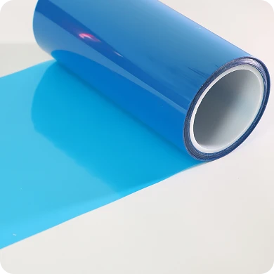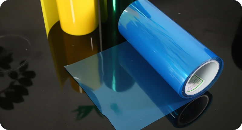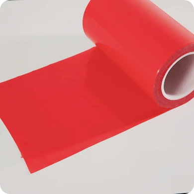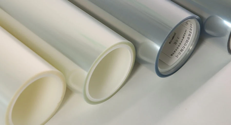
Web breaks, matrix tears, and erratic stripping on a rotary die-cutting line rarely stem from a simple mechanical failure. When converting speeds accelerate past 80 to 100 meters per minute, the primary culprit is almost always a mismatch between dynamic converting stresses and release liner runnability. Standard lab sheets and static release tests do not simulate the rapid shear, instantaneous peel forces, and localized tension spikes that occur during rotary conversion.
Understanding why a release film for die cutting fractures requires looking past nominal datasheet values. Line failures are governed by three primary material factors: the dynamic delamination curve of the silicone coating, base film tensile integrity under tension transients, and triboelectric charge accumulation. Evaluating these micro-mechanisms enables converters to stabilize line tension, prevent anvil cut-through, and choose base films engineered to withstand high-velocity mechanical stresses.
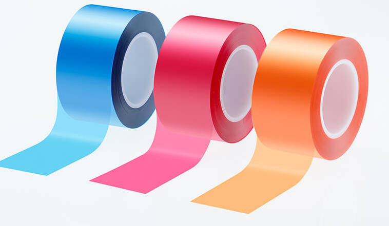
Beyond Static Specs: The Real Mechanics of High-Speed Liner Failure
On a high-speed converting line, materials experience severe viscoelastic deformation. At lower speeds, a release liner has sufficient relaxation time to dissipate stress evenly across the web. Once conversion speeds reach commercial rotary thresholds, that relaxation window closes.
| Converting Operational Regime | Primary Stress Trigger | Material Response Mechanics | Resulting Process State | End Line Condition |
|---|---|---|---|---|
| Low-Speed Converting (Static Relaxation) | Controlled Web Tension | Gradual Elongation across Carrier | Constant Stress Dissipation | Controlled Matrix Peel |
| High-Speed Rotary Converting (Dynamic Shock) | Dynamic Tension Spike | Localized Necking & Yield Failure | Micro-Crack Propagation | Web Break & Line Stoppage |
When web speed doubles, the strain rate applied to both the silicone release layer and the polymeric carrier multiplies. Static quality control checks, such as standard 180-degree peel tests conducted at benchtop speeds, describe how a liner behaves in a warehouse, not in a multi-station rotary press. If a carrier film possesses minor thickness variations or micro-voids along its slit edge, localized stress concentration occurs. Instead of an even, continuous delamination, the converting line encounters micro-stalling, localized web necking, and instantaneous tearing.
Dynamic Release Force vs. Static Testing: The High-Speed Delamination Gap
Why FTM 1 Test Values Lie at 100 m/min
Standard industry peel values—most commonly measured via FINAT Test Method 1 (FTM 1) at approximately 300 mm/min—measure equilibrium release forces. In contrast, an industrial die-cutting line running at 120 m/min strips the liner at peel rates hundreds of times faster.
Silicone polymers exhibit non-Newtonian, viscoelastic properties. As stripping velocity escalates, the apparent release force increases along a non-linear curve known as the velocity sensitivity slope. A liner specified as “easy release” (e.g., 10–15 g/25mm) under standard FTM 1 conditions can easily exhibit dynamic release values three to five times higher at operating speeds. If a formulation uses silicone polymers with high molecular weight distributions or insufficient crosslink density, the release curve steepens drastically, leading converters to face unexpected web drag.
Release Shock and Matrix Tearing During Rapid Stripping
When adhesive passes through the matrix stripping station, separation happens over a fraction of a millisecond. If the release layer exhibits a sharp transition between static friction and dynamic kinetic release, the press encounters an effect known as “release shock.”
Release shock causes momentary tension spikes in the waste matrix skeleton. Because matrix borders are often narrow (frequently under 2 mm in intricate electronic gasket and tape configurations), any sudden jump in stripping resistance exceeds the tensile limit of the unsupported adhesive-carrier matrix, causing a tear. To maintain line continuity, converters require an engineered silicone release film designed with flat release force curves across varying stripping velocities.
| Testing & Operating Parameter | Standard Lab Test (FINAT FTM 1) | High-Speed Production Line | Failure Mode Triggered by Mismatch |
|---|---|---|---|
| Peel Velocity | 300 mm/min (~0.005 m/s) | 60–150+ m/min (1.0–2.5+ m/s) | Premature matrix tearing; release shock |
| Strain Profile | Constant, single-axis pull | Multi-axial cyclic tension | Localized edge fractures; web snap |
| Interfacial Temperature | Ambient room temperature | Frictional heating at idlers & dies | Adhesive transfer; silicone softening |
| Release Dynamics | Equilibrium interfacial peeling | Dynamic viscoelastic peeling | Trapped waste matrix; machine stalling |
Substrate Breakdown: Tensile Limitations and Caliper Variation
MD vs. TD Tensile Balance Under Tension Transients
Even when release chemistry is properly calibrated, physical breakage occurs when the mechanical limits of the underlying carrier film are exceeded. In automated rotary die-cutting lines, PET is preferred over paper liners because of its higher tensile modulus and smooth surface. However, not all polyester films demonstrate identical mechanical profiles under tension.
Biaxially oriented PET liners must maintain a calculated balance between Machine Direction (MD) tensile strength and Transverse Direction (TD) tear resistance. During emergency stops, rapid accelerations, or slight clutch adjustments, tension transients transmit through the web. If an economy-grade carrier lacks sufficient MD tensile modulus, the web elongates elastically. This elongation alters die registration, causes depth-of-cut drift, and creates downstream slack that binds against processing rollers.
Gauge Banding and Die-Cutting Anvil Impressions
Precision rotary converting operates within micron-level clearances. Tooling engineers specify hardened anvils and flexible dies to cut through the face stock and adhesive layers while kissing the silicone interface without penetrating the base liner.
Caliper uniformity across the web profile is critical:
- Positive Caliper Spikes (+2 to +3 µm): Cause the rotary die edge to strike too deeply into the PET carrier, creating micro-notches (anvil impressions).
- Negative Caliper Dips (-2 to -3 µm): Lead to partial cuts in the face stock, causing the matrix to pull and jam downstream.
Micro-notches on a stretched carrier film create severe notch-sensitivity issues. Under constant line tension, microscopic score lines instantly propagate across the web, culminating in sudden transversal web snaps. Running precision conversion requires sourcing a high-tensile PET release film manufactured with rigorous cross-web caliper tolerances to ensure consistent kiss-cutting depth.
Secondary Invisible Culprits: Static Accumulation and Incomplete Silicone Cure
Triboelectric Charging on Fast Roller Paths
As polymeric film moves across non-conductive steel and rubber rollers at high speeds, contact and separation induce continuous triboelectric charge accumulation. Without inline mitigation, electrostatic charges can exceed 15 to 20 kilovolts.
High static fields create three operational failures:
- Matrix Clinging: Stripped matrix material electrostatically clings to anvil rolls, wrap rollers, or the main die, wrapping around rotating components and forcing line shutdowns.
- Dust Attenuation: Uncontrolled charges pull airborne debris directly onto the exposed adhesive face before lamination.
- Web Tracking Drift: Static attraction against grounded metal side plates causes side-to-side web steering instability.
Subsequent Adhesion Loss (SAS) and Silicone Migration
Another common cause of converting failures is incomplete thermal or UV curing of the release coating. When silicone polymers are crosslinked incompletely, unreacted monomers remain free to migrate.
Under tight master roll winding pressure, free silicone monomers transfer directly onto the unprinted backside of the carrier or into the facing pressure-sensitive adhesive. This migration compromises Subsequent Adhesion Strength (SAS). Furthermore, areas with inconsistent curing can exhibit silicone pull-off during conversion, causing adhesive to lock permanently onto the carrier liner and bringing high-speed lines to an immediate halt.
| Observed Line Symptom | Immediate Mechanical Mechanism | Root Material or Chemical Flaw | Preventive Material Specification |
|---|---|---|---|
| Transverse Web Break | Notch-sensitivity failure at die station under operating tension | Cross-web caliper variation inducing die strike-through + low MD tear resistance | Precision gauge control (±1 µm) with balanced biaxial tensile orientation |
| Matrix Stripping Snap | Sudden dynamic release force spike at the stripping beak | Viscoelastically steep silicone formulation (sharp high-speed velocity curve) | Modified silicone polymers engineered for flat high-speed release slopes |
| Waste Matrix Wrap-Around | Electrostatic cling to rotating dies, idlers, and machine frame | Absence of anti-static coatings resulting in high surface resistivity (>1012 Ω/sq) | In-line anti-static treatment achieving surface resistivity of 108–1010 Ω/sq |
| Adhesive Ghosting & Lock-Up | Incomplete separation with adhesive anchoring to the liner | Incomplete silicone cure and free oligomer migration (low SAS %) | Thermal or UV curing verification ensuring SAS retention >90–95% |
How to Engineer Reliability: A Release Film Sourcing & Testing Matrix
To stop unplanned converting downtime, production teams should shift from generic commercial grades to application-engineered materials. Specifying release materials for tight-tolerance, high-speed rotary die-cutting requires verifying mechanical and chemical boundaries during supplier audits and raw material onboarding.
Material Qualification Matrix for High-Speed Die-Cutting
| Quality Parameter | Target Metric / Evaluation Method | Why It Matters on the Converting Line |
|---|---|---|
| Base Film Caliper Uniformity | Total thickness variation within tight micron thresholds across cross-direction | Prevents die impressions, notch-scoring, and liner cut-through during high-pressure kiss-cutting |
| Dynamic Release Profile | Modified high-speed release testing (10 m/min to 60+ m/min) | Ensures release force stays within a controlled range to prevent matrix breakage |
| Cure Verification (SAS %) | Subsequent Adhesion Strength testing (>90–95% depending on spec) | Verifies complete crosslinking and confirms no free silicone will poison adhesive matrices |
| Tensile Modulus (MD/TD) | High yield point under operating web tension | Resists web stretching, maintaining registration and constant tension across dancer arms |
| Surface Resistivity | Anti-static treated surface layer (108 to 1010 Ω/sq where required) | Dissipates triboelectric build-up, preventing matrix wrap around rollers and machine frame |
Implementing this qualification protocol ensures your materials perform predictably. By partnering with technical manufacturers like YINGFEI for custom release liner solutions, converters can match specific adhesive systems—whether acrylic, rubber, or silicone—with carriers that maintain structural integrity at high production speeds.
Frequently Asked Questions on Die-Cutting Liner Runnability
Why does the liner break only at the rotary die cavity and not during straight web passage?
Straight web paths apply uniform, single-directional tensile loads, which polyester carriers handle efficiently. At the rotary die station, the liner experiences simultaneous mechanical compression, knife shear, and instantaneous tension differentials as the waste matrix separates from the converted part. If the die edge strikes the liner even slightly, it creates micro-fissures along the cut line. Combined with the peel tension from the stripping roll, these micro-notches initiate a rapid tear across the web.
Is a thicker PET release film always better for preventing web breakages?
Not necessarily. While upgrading from 50 µm to 75 µm or 100 µm increases absolute breaking strength, it also alters web stiffness, roll weight, and internal bending stresses around small-radius idler rollers and stripping beaks. If the root cause is poor dynamic release, inadequate cure, or erratic cross-web caliper, increasing thickness merely masks the issue while escalating material costs and reducing roll yields. Eliminating web breaks requires solving caliper consistency and dynamic release stability rather than simply adding base mass.
What causes erratic release force differences between the drive side and operator side of the roll?
Cross-web release variance is generally caused by uneven coating application during the silicone crosslinking process. If the coating head exerts non-uniform doctoring pressure, or if drying ovens show transverse temperature gradients, the silicone layer will exhibit varying crosslink densities and coating weights from left to right. This causes the matrix to release easily on one side while snapping or sticking on the other.
Mitigating High-Speed Converting Risks With Engineered Liners
Maximizing throughput on industrial rotary presses is impossible when using commodity liners that fail under dynamic stress. Converting failures like web breaks, deep die cuts, and matrix snaps occur when material properties are treated as static laboratory numbers rather than dynamic mechanical responses.
Reviewing your converting lines, checking base film caliper tolerances, and accounting for high-velocity peel curves allows you to systematically eliminate machine stoppages. When you pair verified mechanical properties with precision-cured silicone chemistries, line speeds can safely scale without increasing waste.
If your plant is experiencing web breaks, matrix tears, or erratic kiss-cutting depth at higher speeds, send your process conditions, line speeds, and adhesive specifications to our engineering team to review line compatibility and request trial roll samples of YINGFEI custom-engineered release films.
Key Takeaways
- Static tests do not predict dynamic performance: Standard FTM 1 release tests operate far below industrial machine velocities; high-speed peeling triggers non-linear release force increases that cause matrix breaks.
- Caliper consistency protects against web breaks: Minor cross-web thickness variations lead to anvil kiss-cut scoring. These score marks act as stress-concentration points that propagate into full web snaps under machine tension.
- Release shock snaps thin matrices: Rapid transitions between static and dynamic peeling generate instantaneous load spikes that rupture narrow matrix borders.
- Static electricity and incomplete curing cause machine jams: Uncontrolled electrostatic charges cause the stripped matrix to cling to rotating tooling, while under-cured silicone transfers to adhesives and destroys bond performance.
- Material specifications must reflect machine realities: Liners must be evaluated using dynamic peel profiles, cross-web caliper uniformity, MD/TD modulus balance, and anti-static surface controls.
FAQ
What is release liner runnability?
Release liner runnability refers to the ability of a silicone-coated backing material to feed through high-speed converting, printing, and die-cutting machinery smoothly without tearing, stretching, creating web breaks, or causing matrix stripping jams.
How does web tension affect release film runnability?
Excessive web tension causes carrier films to stretch elastically, leading to registration loss and web narrowing. Conversely, insufficient or uneven tension causes web flutter, tracking misalignment, and uneven stripping forces that snap delicate waste matrix skeletons.
Can static electricity cause mechanical web breaks on converting equipment?
Yes. Severe electrostatic charges pull the lightweight waste matrix back toward rotating rollers or die cylinders. When the matrix sticks to rotating components, it wraps around the rollers and snaps the continuous web, forcing an emergency press shutdown.