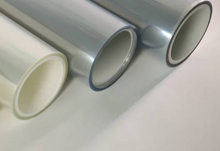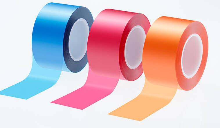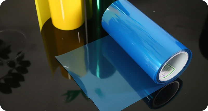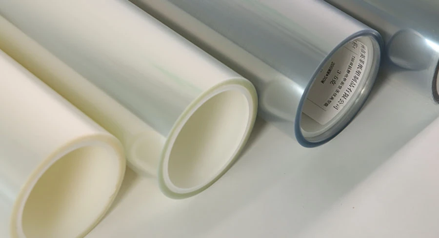
Matrix stripping failure on thin liners occurs when dynamic mechanical peel force exceeds the tensile yield strength of the narrow waste matrix skeleton, triggering sudden web breaks and costly press downtime. During label converting, down-gauging release liners to ultra-thin profiles—such as 23 µm, 19 µm, or 12 µm PET—radially narrows the allowable process operating window. Success or failure is governed primarily by three interconnected variables: liner surface energy and cured silicone release force stability, the viscoelastic flow and cohesive strength of the adhesive layer, and kinetic stress amplification driven by press line speed.
Converting ultra-thin substrates reliably requires balancing mechanical tension parameters with specialized material specifications. This guide breaks down the physical separation dynamics of thin liners, details root-cause mechanisms across chemical and mechanical interfaces, provides an engineering diagnostic matrix, and outlines key technical criteria for selecting the proper release film for label converting.

The Engineering Trade-off: Thin Liner Down-Gauging vs. Matrix Stripping Reliability
The ongoing transition across industrial converting toward thinner release liners reduces raw material consumption, decreases roll-change downtime through longer continuous roll lengths, and lowers freight footprint per converted unit. However, transitioning from conventional 30 µm or heavier PET liners to ultra-thin gauges introduces severe mechanical vulnerabilities.
| Liner Classification | Typical Thickness Range | Operating Process Window | Mechanical & Defect Response |
|---|---|---|---|
| Conventional Liner | 30 µm and above | Wide Operating Window | High web modulus; absorbs localized tension spikes and tolerates minor die-cutting depth variations |
| Thin Liner | 12 µm to 23 µm | Narrow Operating Window | Low tensile modulus; defect-sensitive stress peaks transfer directly to the matrix neck, inducing tears |
When liner caliper decreases, transverse and machine-direction stiffness drop disproportionately. In conventional-gauge laminates, a rigid liner absorbs localized tension surges from mechanical vibration or adhesive tack anomalies. In ultra-thin liners, that structural dampening is lost. Any minor micro-fracture from die-cutting, adhesive flow ooze, or sudden release force spike shifts stress directly into the thinnest web matrix bridges, precipitating immediate matrix tear-outs.
Physics of Matrix Separation: The Tri-Factor Interplay on Thin Liners
During continuous rotary die-cutting, matrix stripping functions as a continuous high-speed peel test. The total pulling tension applied to the matrix rewind spool (Fweb) must remain below the ultimate tensile strength of the waste matrix material, while exceeding the dynamic peel resistance (Fpeel) required to shear the adhesive layer and cleanly separate the face stock from the release film.
Tensile Rigidity and Modulus Loss in Down-Gauged Liners
As liner thickness decreases, the cross-sectional area supporting longitudinal tension is reduced. Under high web tension, thin liners experience micro-elongation under mechanical strain. If the thin liner stretches even fractions of a percent more than the face stock during lamination or cutting, localized shearing occurs at the interface. This elastic mismatch leaves residual stress zones where the matrix skeleton can tear during vertical separation.
Peel Angle Dynamics and Stress Concentration at the Stripping Edge
The geometry of the stripping point—governed by the stripping bar radius or the take-off roller configuration—determines how peel stress distributes across the separation meniscus:
- Acute Peel Angles (< 90°): Maximize normal tensile cleavage stress at the immediate peel line. This configuration speeds up initial separation but concentrates peak stress over a narrower contact line, making thin liners prone to edge tears if adhesive tack is aggressive.
- Obtuse Peel Angles (> 90° to 135°): Shift stress into a shear-dominant state. While this dampens sudden peel spikes, it prolongs the time adhesive fibrils remain in tension, increasing drag if adhesive flow has created micro-bridges between cut edges.
Root Cause 1: Liner Surface Energy, Silicone Chemistry, and Release Force Stability
The surface chemistry of the silicone-coated backing directly establishes the baseline resistance encountered during separation.
Differential Release Force: Static vs. High-Speed Kinetic Release
Release force values determined at standard laboratory speeds (typically 300 mm/min via standard test methods like FINAT FTM 1 or 2) do not correlate linearly with modern press converting speeds (100 to 300 m/min). At production line speeds, release force increases non-linearly.
| Metric Component | Standard Lab Evaluation | High-Speed Converting Condition | Operational Impact on Thin Liners |
|---|---|---|---|
| Test Speed | 0.3 m/min (approx. 12 in/min) | 100 – 250+ m/min | Dynamic force can climb to 2x–5x baseline laboratory values |
| Stress Type | Controlled quasi-static peel | Viscoelastic shock cleavage | Concentrates peak pull on delicate matrix ladders |
| Material Behavior | Equilibrium interfacial release | Rate-dependent polymer deformation | Demands silicone coated release film solutions with flat release force gradients |
If the cured silicone network exhibits a steep release curve as speed escalates, the matrix web is subjected to sudden dynamic snatching forces that trigger stripping breaks.
Incomplete Silicone Curing, Migration, and Subsequent Adhesive Lock-Up
Thermal curing or UV curing of the polydimethylsiloxane (PDMS) release layer must achieve complete cross-linking. If unreacted silicone oligomers remain:
- Low-molecular-weight siloxanes migrate into the pressure-sensitive adhesive (PSA) matrix during storage.
- Incomplete curing can cause localized areas of high release force—commonly termed “silicone lock-up” or dry spots.
- When the die-cut matrix reaches a patch of inconsistent release coating at 150 m/min, the sudden spike in separation resistance instantly breaks the waste matrix.
Root Cause 2: Adhesive Flow Dynamics and Viscoelastic Cavitation
Pressure-sensitive adhesives are viscoelastic materials exhibiting both liquid-like flow and elastic-solid properties. Their behavior during die-cutting and stripping depends directly on time, temperature, and shear rate.
Cold Flow and Edge Ooze (Adhesive Bleed) After Slitting
During rotary die-cutting, the cutting die blade compresses the face stock and adhesive layer, severing them against the release liner surface. Because PSAs are viscous liquids under prolonged low-frequency conditions, they undergo cold flow.
If converted rolls sit under rewind tension, or if ambient plant temperatures soften the adhesive formulation, the adhesive flows laterally back together across the die-cut cut lines. This phenomenon—adhesive bleed or edge ooze—effectively spot-welds the label perimeter back to the waste matrix. When the matrix is pulled upward, it must mechanically shear through these re-knit adhesive bridges, dramatically increasing the required stripping force.
High Strain-Rate Cleavage: Viscoelastic Filament Formation
At high separation velocities, the adhesive inside the peeling meniscus undergoes cavitation and rapid extension into microscopic filaments (fibrils). Clean separation requires these filaments to detach cleanly from the release coating surface rather than stretching excessively or undergoing cohesive failure. When working with aggressive tack adhesives (such as high-tack emulsion acrylics or rubber-based hot melts), the energy required to break these viscoelastic filaments can easily exceed the tensile limit of down-gauged waste matrix lines.
Root Cause 3: Line Speed Scaling and Operational Process Windows
Increasing machine speed modifies every physical interaction at the peeling interface simultaneously.
Strain Rate Dependence of Pressure-Sensitive Adhesives
As line speed increases, the strain rate applied to the adhesive rises by several orders of magnitude. Under high strain rates, viscoelastic polymers shift toward glassy behavior: their effective modulus increases, energy dissipation peaks, and dynamic peel resistance spikes. Consequently, a release liner that strips effortlessly at 40 m/min setup speed can exhibit extreme resistance when the operator ramps the machine to 180 m/min.
| Line Speed Regime | Strain Rate on PSA | Adhesive Rheological Response | Peel Resistance Behavior | Risk Level on Thin Liners |
|---|---|---|---|---|
| Low Speed (< 50 m/min) | Low (101 – 102 s-1) | Rubbery plateau; high chain mobility | Low baseline peel resistance; smooth separation | Minimal break risk |
| Moderate Speed (50–120 m/min) | Intermediate | Polymer relaxation lags deformation rate | Linear increase in dynamic peel force | Manageable under steady tension |
| High Speed (> 150 m/min) | High (> 104 s-1) | Glassy transition; peak viscoelastic dissipation | Exponential resistance spike; aggressive filament drag | Critical matrix break risk zone |
Tension Fluctuation and Inertial Jolt at High Converting Speeds
Waste matrix rewind spindles utilize mechanical friction clutches or closed-loop servo drives. As press speeds scale:
- Out-of-round matrix rewind rolls generate cyclic tension pulses.
- Rapid machine acceleration causes instantaneous inertial spikes before tension controllers can compensate.
- In thin liners lacking tensile mass, these micro-second tension spikes cannot be absorbed elastically, leading directly to matrix breaks at the stripping bar.
Systematic Troubleshooting Matrix: Diagnosing Matrix Break Root Causes
When matrix stripping failures occur on thin liner constructions, process engineers should systematically isolate tooling, chemical, and substrate variables using the following diagnostic framework.
| Observed Defect Symptom | Underlying Physical Mechanism | Press / Tooling Adjustment | Substrate / Material Verification |
|---|---|---|---|
| Matrix web snaps cleanly at sharp matrix corners | Stress concentration caused by sharp geometry combined with high stripping angle | Increase stripping bar radius; reduce stripping angle to relieve normal cleavage stress | Verify cross-directional (TD) tensile strength and elongation profile of face stock |
| Matrix breaks accompanied by adhesive stringing/haze | Adhesive bleed (re-knitting) or high viscoelastic filament formation | Reduce web temperature; inspect die sharpness for adhesive smear; increase stripping speed slightly to promote brittle interfacial release | Check adhesive coat weight; confirm adhesive formulation has sufficient internal cohesion |
| Labels lift off liner and travel into waste matrix (fly-away) | High dynamic release force relative to adhesive bond strength to face stock | Adjust stripping angle closer to 180°; ensure minimal web wrap around stripping roller | Select a stable release film for thin liner converting featuring an easier (lower) release force profile |
| Intermittent snapping across roll width with audible popping | Inconsistent silicone cure, silicone void spots, or local caliper variations | Check impression cylinder for runout or debris; inspect die blades for uneven depth penetration | Perform differential release force testing across web width; verify residual adhesion percentage |
| Matrix breaks primarily during machine acceleration | Closed-loop rewind tension overshoot or inertia spike on waste wind-up | Tune servo tension acceleration curves; reduce base unwind and matrix rewind tension setpoints | Confirm liner tensile modulus specifications with substrate supplier |
Material Selection Framework: Critical Release Film Parameters for High-Speed Thin Liners
Preventing matrix stripping failures when converting thin liners requires evaluating PET release film beyond basic nominal caliper and standard room-temperature static release figures.
| Evaluation Dimension | Key Engineering Parameter | Target Performance Standard | Failure Mode Prevented |
|---|---|---|---|
| Mechanical Integrity | MD / TD Tensile Modulus & Gauge Uniformity | Minimal caliper variation across web; high tensile stiffness | Die strike-through into PET core; web stretching; uneven cutting |
| Surface Energy Control | Silicone Cross-linking & Residual Adhesion | > 90% residual adhesion; zero free-silicone transfer | Adhesive lock-up; localized release force spikes; contamination |
| Dynamic Peel Stability | High-Speed Release Force Gradient | Flat kinetic release curve up to 250+ m/min | Matrix snatching; high-speed peeling break-offs |
| Thermal Stability | Dimensional Shrinkage Resistance | Low residual shrinkage under operational curing temperatures | Web curling; edge curl during stripping; tracking misalignment |
Tensile Strength (MD/TD) and Caliper Uniformity Requirements
Thin PET substrates (down to 19 µm or 12 µm) rely entirely on biaxial orientation quality to achieve the mechanical rigidity necessary to withstand die-cutting anvil impacts:
- Machine Direction (MD) Tensile Modulus: Must remain sufficiently high under operational tensions to prevent liner necking or plastic deformation under die blades.
- Caliper Variation (Gauge Uniformity): Ultra-thin liners require tight gauge tolerances. Excessive thickness variation across the web creates irregular cutting depths: the die blade will either under-cut (causing uncut adhesive strands and matrix tears) or over-strike through the silicone into the PET core (causing adhesive lock-in and liner breaks).
Release Force Range Tuning and Thermal Dimensional Stability
- High-Speed Release Curve Gradient: Select release coatings specifically formulated to maintain a flat release profile as line speed increases, preventing dynamic resistance spikes at speeds above 150 m/min.
- Curing Integrity and Residual Adhesion: High-efficiency thermal curing systems are essential to minimize free siloxanes, maintaining residual adhesion values typically exceeding 90% to avoid chemical interference with downstream PSA layers.
- Thermal Dimensional Shrinkage: The PET carrier film must exhibit minimal thermal shrinkage during coating and curing stages to ensure roll flatness, uniform lay-flat behavior, and zero curl during high-speed converting runs.
Key Takeaways
- Down-gauging narrows the converting window: Reducing release liner thickness removes structural elasticity, meaning adhesive ooze, micro-cuts, or sudden peel force spikes translate directly into matrix web breaks.
- Static lab tests do not predict dynamic behavior: Release force measured at 0.3 m/min can climb by multiples at industrial press speeds (100–250 m/min) if the silicone coating possesses a steep velocity-dependent release curve.
- Adhesive rheology is critical: Adhesive bleed across cut lines and viscoelastic filament formation increase matrix drag; addressing it requires managing process temperatures, tool sharpness, and adhesive cohesive strength.
- Stripping geometry dictates stress distribution: Modifying stripping bar radii and peel angles shifts the mechanical balance between normal tensile cleavage and shear stress, helping protect fragile matrix necks.
- Base film mechanical properties matter: High MD/TD tensile modulus and tight thickness tolerances are prerequisites for ultra-thin PET release liners to prevent die strike-through and intermittent matrix tearing.
FAQ
What is the optimal peel angle to prevent matrix breaks on high-speed label presses?
For thin liners running at elevated line speeds, an obtuse peel angle between 110° and 135° over a small-radius stripping bar or roller typically delivers the most stable separation. This geometry reduces peak normal cleavage stress and leverages shear detachment, preventing sudden snatching breaks on delicate matrix skeletons.
How does ambient temperature affect adhesive flow during matrix stripping?
Higher ambient temperatures decrease pressure-sensitive adhesive viscosity, promoting cold flow and edge ooze across cut lines after die-cutting. This creates re-knitted adhesive bridges that sharply increase separation resistance. Maintaining controlled plant temperatures and keeping web temperatures stable helps preserve adhesive cohesion during stripping.
Can increasing silicone coat weight eliminate matrix stripping issues on thin liners?
No. Simply increasing silicone coat weight does not resolve matrix breaks and may cause coating transfer, poor anchorage, or silicone misting during manufacturing. The critical performance factors are the cross-linking density of the cured silicone, the flatness of its high-speed release curve, and the thickness uniformity of the underlying PET carrier film.
How can a converter distinguish between dull die tooling and liner silicone lock-up?
Inspect the cut edges of both the label and the liner under magnification. A dull die produces crushed edges, irregular micro-tears in the face stock, or distinct die-strike witness marks into the PET backing. Silicone lock-up presents as clean, sharp die cuts where the matrix fails because the adhesive remains anchored to patches of the liner surface without mechanical film damage.