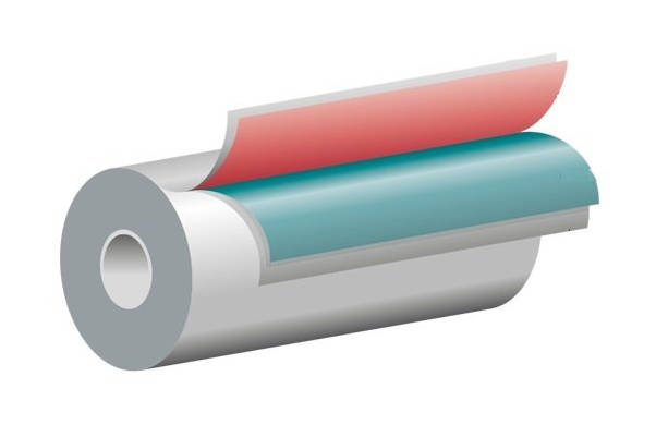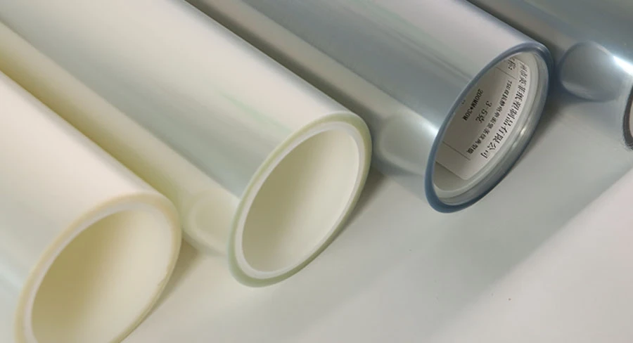
When an automated converting line experiences web flutter, tracking drift, edge curl, or sudden web breaks at the unwind stand, operators often attempt to correct the issue by recalibrating brake pressure, adjusting dancer arm pneumatic load, or shifting edge guide sensors. In many processing lines, however, the root cause is not mechanical instability at the unwind stand itself, but latent stress locked into the material during upstream slitting and rewinding. The internal architecture of a slit roll—known as its roll build—dictates how stored tension discharges as the roll diameter decreases.
When converting rolls of high-performance release film, poor roll structure introduces severe instability into rotary die-cutting, silicone coating transfer, and high-speed lamination. Understanding how wound-in stress, air entrapment, and slit edge geometry interact allows converting engineers to isolate roll build defects before web processing begins. This guide analyzes the mechanical origins of roll defects such as telescoping, explains the core winding physics governing film converters, and outlines diagnostic audit procedures to stabilize unwind tension on production lines.
The Downstream Reality: Why Unwind Failures Start at the Rewind Station
Roll build refers to the physical density, radial stress distribution, and edge alignment established throughout a roll of film from core to outer wrap. An ideal roll functions as a balanced pressure vessel: it remains firm enough to maintain its cylindrical shape during transit, yet elastic enough to absorb minor caliper variations without permanently distorting the film substrate.
When upstream slitter-rewinders wind rolls with inconsistent internal tension profiles, that stress remains trapped between layers. As the roll unwinds downstream at high line speeds, the trapped stress discharges unevenly:
- Tension Surges and Baggy Webs: If inner layers were wound too loosely relative to outer wraps, the release film slips internally as the unwind brake engages, causing abrupt web slackness followed by tension spikes that stretch or snap thin carrier liners.
- Tracking Instability: Variations in wound-in tension across the roll width cause the web to steer toward the tighter side, forcing active edge-guide actuators to cycle continuously and often exceed their stroke limits.
- Registration Drift in Die-Cutting: Uneven layer-to-layer stress release introduces localized elongation along the web path, disrupting repeat-length registration in multi-station rotary die-cutting.
- Surface Scuffing and Coating Disruption: Interlayer slippage rubs cured release surfaces against adjacent polyester backings, causing localized release value fluctuations or micro-scratches that impair adhesive release uniformity.
Addressing these disruptions requires isolating the specific mechanical failure modes generated during slitting and rewinding rather than treating downstream web instability in isolation.
Decoding Roll Telescoping: What Causes the Sideways Creep?
Telescoping—often referred to in severe cases as roll dishing or mushrooming—is an axial displacement defect where individual film wraps slide sideways relative to one another, pushing the core inward or projecting outer layers outward in a conical shape.
| Evaluation Parameter | Normal Uniform Roll Build | Telescoped / Dished Roll Build |
|---|---|---|
| Physical Geometry | Flush, planar sidewalls perpendicular to core axis | Conical, stepped, or dished edge profile with displaced wraps |
| Stress Distribution | Controlled radial pressure with stable taper tension | Inverted hoop stress squeezing soft, low-tension inner layers |
| Interlayer Traction | Uniform friction lock preventing lateral wrap slippage | Axial shear exceeding static interlayer friction limits |
| Unwind Stability | Smooth rotation, stable tracking, minimal edge guide cycling | Continuous lateral web wander, edge curl, and brake-induced slippage |
Telescoping occurs when the axial forces within the wound roll exceed the static interlayer friction holding adjacent film layers in position. Several physical factors accelerate this failure mode in converted release liners:
1. Extremely Low Coefficient of Friction (COF)
Polyester (PET) and polyolefin films coated with crosslinked polydimethylsiloxane (PDMS) silicone formulations have exceptionally low surface energy and minimal friction coefficients. Because silicone chemistries minimize adhesion to pressure-sensitive adhesives, they also reduce mechanical traction between the coated face and the uncoated film reverse side. Without sufficient radial clamping pressure, adjacent wraps slide axially under minimal lateral force.
2. Inverted Radial Stress Distribution (Loose Core Winding)
When a roll is wound with loose wraps near the core and tight wraps toward the outside, the exterior layers exert compressive hoop stress on the interior foundation. As the outer layers contract, they squeeze the lower-tension inner layers. Because the material cannot compress radially past its physical density limit, the trapped inner wraps shear along the path of least resistance: sideways out of the roll face.
3. Lateral Air Entrainment at High Line Speeds
At elevated winding speeds, a boundary layer of ambient air is pulled into the closing nip between the incoming web and the rewinding roll. If this air layer is not consistently excluded, it forms a fluid micro-cushion that separates adjacent wraps. This air pocket reduces effective surface contact to near zero, allowing the web to drift axially before the air slowly bleeds out through the roll edges.
The TNT Principles: How Tension, Nip, and Torque Determine In-Roll Stress
Achieving uniform roll structure across sensitive converted substrates requires balancing three primary mechanical variables: Tension, Nip, and Torque (the TNT principles). In specialized converting of custom-slit release film, an error in any single parameter undermines the stability of the entire roll build.
| TNT Parameter | Primary Mechanical Function | Setting Error: Too Low | Setting Error: Too High |
|---|---|---|---|
| Tension (T) | Governs longitudinal web strain and baseline wound-in stress. | Web wander, tracking weave, loose roll package integrity. | Film elongation, core crushing, spoke buckling. |
| Nip (N) | Excludes boundary layer air and mechanically locks the outer wrap. | Air entrainment, soft rolls, lateral wrap slippage. | Caliper distortion, pinholing, silicone transfer defects. |
| Torque (Q) | Drives core rotation and anchors foundational inner wraps. | Core slip, roll telescoping during unwind braking. | Core collapse, radial cracking, roll bursting. |
1. Tension (T) and Taper Tension Profiling
Web tension supplies the baseline elastic strain to the film before it reaches the rewind roll. However, maintaining constant web tension from core to full diameter creates a structurally unsound roll; as outside layers accumulate, their combined tensile load crushes the core wraps.
Modern slitter-rewinders must utilize a programmed taper tension profile, systematically decreasing winding tension as roll diameter expands. For thin PET release films, converters typically program a 10% to 30% linear or hyperbolic tension taper. This gradual reduction prevents outer bands from squeezing the softer inner foundation while preserving adequate web control.
2. Nip (N) and Air Boundary Exclusion
The nip roller exerts direct mechanical force against the face of the rewinding roll at the point of web engagement. Its primary function is to meter and displace the boundary layer of air carried along the film surface.
- Insufficient Nip Force: Traps an uncontrolled air wedge, causing loose roll density, low interlayer traction, and delayed telescoping during handling.
- Excessive Nip Force: Induces mechanical over-stretching along localized thickness bands, leading to permanent gauge-band deformation and web bagging.
3. Torque (Q) and Differential Slip Control
Torque represents the rotational driving force applied directly through the rewind shaft to the roll core. On multi-roll slitter shafts, slight caliper variations across the parent master roll cause individual slit lanes to wind at subtly different linear speeds.
If slit rolls share a locked friction shaft, rolls positioned on thicker gauge lanes wind tighter than adjacent rolls on thinner lanes. Dedicated converting machinery mitigates this through differential friction shafts, where individual internal friction cores slip independently under precise pneumatic or mechanical bias, ensuring identical torque transfer across every slit lane.
Beyond Telescoping: Secondary Roll Build Defects Crippling Your Unwind
While telescoping represents the most visually obvious winding failure, secondary roll build defects can cause comparable scrap rates on downstream high-speed production lines:
| Roll Build Defect | Physical Manifestation | Direct Mechanical Cause | Impact on Downstream Unwind |
|---|---|---|---|
| High Edges / Ridges | Elevated outer ridges along roll margins | Dull slitting blades; micro-burrs accumulating layer upon layer | Stretched film margins, localized edge flutter, web wrinkles |
| Baggy Lanes | Loose, sagging web sections across roll center | Master roll gauge bands accumulating without oscillation | Uneven web contact, poor laydown on vacuum drums, air pockets |
| Core Collapse | Deformed or crushed core interior | Excessive wound-in stress; insufficient core crush rating | Chuck slippage, inability to load shaft, severe rotational bounce |
| Spoking | Radial zig-zag distortion lines on roll sidewalls | Severe mismatch between tight outer wraps and loose core wraps | Periodic tension spikes per revolution, active dancer bouncing |
High Edges and Edge Ridges
When shear, razor, or score slitting blades become dull, misaligned, or improperly canted, they slightly burnish or deform the slit edge of the film. This localized deformation creates a microscopic lip or burr along the roll margin. Over thousands of continuous wraps, this minute lip stacks into an elevated ring—known as a high edge or ridge—around the outer roll circumference. When unwound downstream, the over-stretched edge becomes longer than the web body, causing edge flutter, wrinkles, and improper web laydown on vacuum drums.
Baggy Lanes (Slack Web Centers)
Polyester film master rolls naturally possess minor cross-directional thickness variations (gauge bands). During continuous center rewinding without web oscillation or randomized slitting, a thicker lane repeatedly winds over itself, forming a localized band of elevated diameter. This concentrated band bears the full tension load of the roll, stretching the film beyond its elastic yield point. When unwound, this stretched area manifests as a loose, sagging web lane that wrinkles during laminating or coating passes.
Core Collapse and Core Slippage
When excessive taper tension or high wound-in stress concentrates near a low-strength fiber or plastic core, the cumulative radial pressure can exceed the core’s beam and crush resistance. The core collapses inward, deforming into an oval shape that will not seat onto downstream mechanical chucks or expanding air shafts. Conversely, if the core wraps were applied with inadequate torque, the core breaks loose and spins freely inside the roll when downstream unwind brakes apply stopping torque.
Spoking
Spoking appears as radial distortion lines radiating outward across the roll sidewall, resembling bicycle wheel spokes. This defect indicates that the internal shear stress within the roll has exceeded its structural capacity, causing localized layers to buckle in a zig-zag pattern. Spoked rolls generate periodic tension pulses at the unwind stand with every revolution, making stable web tracking impossible.
Diagnostic Guide: How to Inspect Roll Quality Before Loading the Unwind
Catching roll build defects before loading raw material onto high-speed production lines prevents web breaks, saves setup time, and avoids damaged converting tools. Plant technicians can evaluate incoming roll integrity using four inspection stages:
| Inspection Stage | Evaluation Focus | Acceptance Criteria | Primary Rejection Triggers |
|---|---|---|---|
| Stage 1: Sidewall Planarity | Visual inspection with straightedge across roll face | Continuous flat sidewalls with no visible lateral step-faults | Wrap displacement exceeding 0.5 mm; dishing or conical steps |
| Stage 2: Core Concentricity | Inner core diameter and sidewall seat inspection | Symmetrical round core without internal gouging or score marks | Oval core deformation; crushed core walls; loose core fit |
| Stage 3: Hardness Profile | Electronic Schmidt hammer or rebound hardness testing | Uniform hardness traverse across width (variation within 3–5 pts) | Steep center drops; narrow hard bands exceeding baseline thresholds |
| Stage 4: Dynamic Unwind | In-line tension sensors and dancer arm movement | Smooth, stable dancer position during speed acceleration/braking | Violent dancer oscillation; cyclic load-cell tension spikes |
1. Visual Sidewall and Edge Planarity Inspection
Place a precision straightedge across the roll face from the core to the outer wrap.
- The sidewall should be planar and smooth. Discontinuous step-faults where groups of wraps shift outward indicate air entrainment bursts or sudden tension changes during slitting.
- Inspect the roll edges for telltale “fuzzy” burrs, white dust, or ragged rims, which signal dull slitting knives that will cause edge tears under tensile load.
2. Core Integrity and Concentricity Check
Inspect the inner diameter of the core. The core must remain concentric and free from internal paper delamination, plastic crushing, or rotational score marks. A damaged or out-of-round core causes severe roll bounce at high rotation speeds, leading to rapid dancer arm oscillation and web breaks.
3. Non-Destructive Hardness Profiling
Evaluate the radial density profile across the width of the roll using a non-destructive testing instrument, such as an automated roll hardness tester, a ParoTester, or a calibrated Schmidt hammer.
- Take multiple hardness measurements across the roll face from the left slit edge to the right slit edge.
- Record readings from the outer wraps down toward the core zone on partial rolls.
- The readings should show a consistent profile across the roll face without localized hardness spikes exceeding three to five points. A steep hardness drop toward the center indicates an under-tensioned lane prone to web wander.
4. Dynamic Unwind Diagnostics
During initial line threading and low-speed run-in, observe the mechanical indicators at the unwind station:
- Dancer Arm Stability: A properly wound roll produces a steady dancer arm position. Rapid vertical oscillations that correlate with roll rotation indicate an eccentric core, severe high edges, or elliptical roll deformation.
- Load Cell Deviation: If tension sensors display rhythmic, cyclic tension swings, the roll build contains trapped stress variations or uneven radial density.
Manufacturing Standards: What to Demand from Your Release Film Converter
Preventing downstream converting failures requires partnering with release film manufacturers and slitting specialists who maintain rigid mechanical controls throughout their processing plants. When evaluating suppliers of precision release film rolls, production managers and procurement engineers should verify specific equipment and quality assurance capabilities:
Dedicated Center-Surface Slitter Rewinders
Conventional center-wind shafts struggle to isolate tension from nip pressure as roll diameters increase. Tier-one converters utilize center-surface rewind configurations where independent driven surface drums control boundary air displacement and nip loading, while independent center-drive motors govern internal wound-in torque.
Dynamic Differential Shafting Systems
To prevent gauge-band variations from creating tight and loose rolls across the same slitter set, converters should use independent differential friction shafts. These mechanisms compensate for web thickness variations across the master roll width by allowing each core to slip at its specific required linear speed.
Real-Time In-Line Slit Edge Inspection and Web Cleaning
Slitting PET film generates microscopic polymer dust if shear knife overlap, rake angle, or blade sharpness deviates from exact standards. Modern slitting facilities incorporate automated edge-break inspection cameras and contact or non-contact web cleaning systems to remove slit debris before it winds into the roll and dents the release coating.
Closed-Loop Taper Tension Automation
Advanced converting equipment uses real-time diameter calculation combined with load-cell feedback to automatically adjust drive motor torque. This maintains a programmed taper tension curve across the entire run, preventing loose inner cores and overtight outer layers.
| Procurement Parameter | Recommended Industry Specification | Technical Rationale |
|---|---|---|
| Core Material & Diameter | Heavy-wall dust-free ABS plastic or treated paperboard (3″ or 6″) | Prevents core deflection under radial pressure; eliminates fiber dust |
| Slit Width Tolerance | Exact tolerance specified per drawing (e.g., ±0.5 mm) | Guarantees lane alignment on automated multi-tool converting stations |
| Sidewall Step Tolerance | Maximum permissible edge step < 0.5 mm | Precludes layer slippage, air entrainment pockets, and edge damage |
| Hardness Traverse Range | Pre-agreed target range with < 5-point variance across roll face | Assures uniform layer-to-layer stress release during unwind tension drops |
| Splice Standard | Zero-splice or clear ultrasonic/butt splice with precise marking | Prevents blade jamming, tool damage, and coating transfer flaws |
Stabilizing Converting Operations Through Controlled Roll Architecture
Unwind stability is an engineered mechanical property established during slitting and rewinding, not an operational variable left to chance on the factory floor. When release film rolls are wound with improper tension profiles, inadequate air exclusion, or unmanaged edge stress, the resulting defects—from subtle gauge bands to severe telescoping—directly cause downstream downtime, web breaks, and product scrap.
By auditing incoming roll hardness, inspecting roll edge geometry, and requiring suppliers to maintain closed-loop taper tension and differential slitting standards, converters can eliminate upstream root causes and maintain smooth, high-speed line operations.
If you are experiencing web breaks, edge curl, or unwind tension instability on your converting lines, contact the technical converting team at YINGFEI. Our specialists can review your slitting parameters, evaluate roll hardness profiles, and provide engineered sample rolls of custom-slit release film configured to stabilize your manufacturing process.
Key Takeaways
- The Root Cause of Unwind Problems: Downstream unwind instability, tension spikes, and tracking drift frequently originate from poor roll build architecture created during upstream slitting and rewinding rather than mechanical faults at the unwind stand.
- The Physics of Telescoping: Roll telescoping occurs when the axial shear stress inside a roll exceeds the interlayer friction of the film. This failure mode is amplified on release films due to the naturally low coefficient of friction of crosslinked silicone surfaces.
- The TNT Framework: Stable roll structure requires balancing Tension (longitudinal strain), Nip (air boundary layer exclusion), and Torque (core drive transmission). Taper tension must decrease gradually as roll diameter expands to prevent loose cores and crushed inner layers.
- Secondary Structural Defects: Dull slitting blades create edge ridges and high edges that stretch film margins, while master roll thickness variations create baggy lanes that wrinkle during downstream coating and laminating.
- Pre-Load Quality Audits: Plants can detect winding defects before processing by checking sidewall planarity with a straightedge, verifying core roundness, and conducting non-destructive roll hardness tests across the roll width.
- Converter Requirements: To ensure reliable roll performance, film buyers should require suppliers to utilize center-surface rewinding, closed-loop taper tension controls, and dynamic differential friction shafts.
Frequently Asked Questions (FAQ)
What is the difference between roll dishing and roll telescoping?
Telescoping and dishing refer to the same fundamental axial displacement defect where individual film wraps slip sideways relative to one another. “Telescoping” typically describes progressive, uniform conical displacement of inner or outer wraps, whereas “dishing” describes non-uniform, dish-shaped curvature across the roll face caused by severe localized layer slip.
How does silicone release coating increase the risk of roll telescoping?
Silicone release coatings substantially lower the coefficient of friction (COF) of the substrate. Because there is less surface traction between the silicone-coated side and the uncoated film backing, adjacent wraps slide against each other under lower axial and radial forces than untreated plastic films, requiring tighter slitting and tension controls.
What is taper tension, and why is it necessary for PET release film rolls?
Taper tension is a programmed reduction in web tension as the rewinding roll increases in diameter. If constant tension is maintained from core to finish, the compressive force of accumulating outer wraps crushes the inner layers, causing core collapse or telescoping. A 10% to 30% taper profile balances internal pressure throughout the roll.
Can roll hardness testing damage a coated release film roll?
Non-destructive roll hardness testers, such as modern electronic Schmidt-type hammers or calibrated impact rebound testers, do not damage thick industrial films when used correctly. However, for ultra-thin or optically critical release films, testing should be conducted only on the outermost wraps before trimming, or via non-contact ultrasonic and optical sidewall audit tools.
What causes a slit release film roll to feel soft on one side and hard on the other?
This condition is almost always caused by cross-directional thickness variations (gauge bands) in the raw master roll. The thicker side of the web winds with a larger effective diameter on each revolution, drawing higher tension and forming a hard band, while the thinner lane receives less relative tension and forms a soft, slack roll profile.