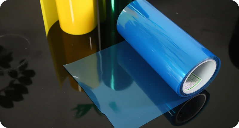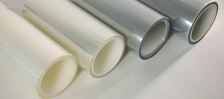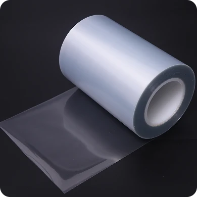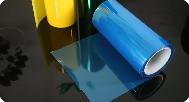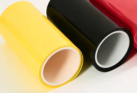
Selecting the right PET release liner for OCA (optically clear adhesive) bonding requires balancing peel force differentials, surface defect limits, chemical compatibility, and static dissipation. In optical display lamination, a carrier film does not merely protect the adhesive during transport; it governs adhesive wet-out, prevents optical distortion, and determines automated die-cutting and lamination yield. Selecting an incompatible liner leads to bubble entrapment, delamination, residual silicone transfer, or electrostatic discharge (ESD) failures on sensitive capacitive touch panels.
This guide outlines the critical engineering criteria for evaluating an optical-grade PET release liner, compares silicone and non-silicone release chemistry, explains differential release ratios, and provides a four-step framework for display lamination production lines.
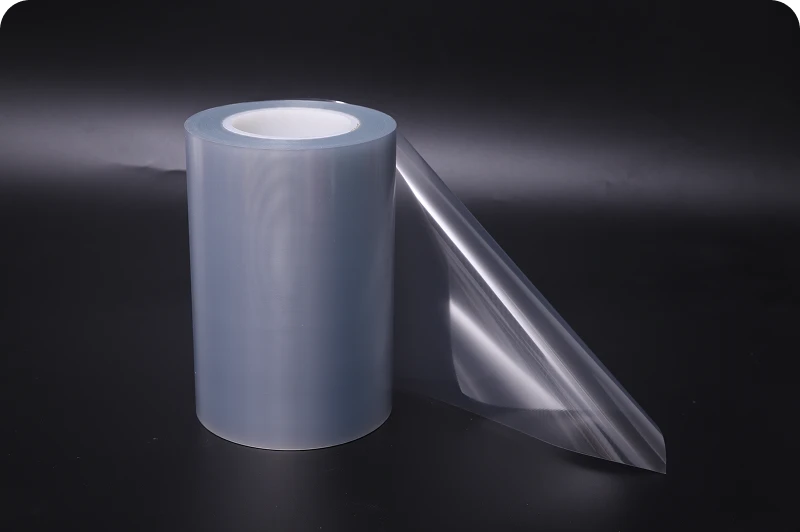
The Impact of Carrier Films on Display Optical Yield
In display manufacturing—including smartphones, tablets, automotive central information displays (CIDs), and industrial touch modules—the carrier film functions as the precision casting foundation for optical adhesives. Standard packaging or industrial films allow minor surface roughness variations, micro-scratches, and additive migration. In contrast, an optical-grade PET release film used for OCA carrier applications must meet strict optical uniformity standards.
If the liner’s surface contains microscopic defects such as gels, orange peel, or pinholes, these irregularities imprint directly onto the soft, viscoelastic OCA layer. Once transferred, these indentations form unbonded voids and micro-bubbles during room-temperature vacuum lamination, which cannot always be removed even during high-pressure autoclave cycles.
Furthermore, poor dimensional stability causes uneven tension during high-speed roll-to-roll conversion, inducing shear stress in the adhesive and resulting in edge oozing or dimensional distortion of the display stack.
Critical Engineering Parameters for OCA Liners
Display process engineers evaluate five core parameters when qualifying a PET carrier liner for optically clear adhesives:
| Parameter | Technical Relevance | Failure Mode if Out-of-Spec |
|---|---|---|
| Residual Adhesion Rate (RAR) | Measures unreacted siloxane transfer | Reduced tack on cover lens glass |
| Release Force Profile | Flat peel curve across variable peel speeds | Liner chatter, adhesive tear-off |
| Surface Purity & Caliper | Low Ra roughness, low gel count | Imprinted optical voids, display haze |
| Dimensional Stability | Thermal shrinkage under heat and tension | Web curl, layer registration slip |
| Electrostatic Decay Time | Surface resistance (single/double side) | Cleanroom particle attraction |
Residual Adhesion Rate and Extractables
Unreacted low-molecular-weight siloxanes or coating additives can migrate into the OCA matrix. This migration lowers the surface energy of the adhesive, reducing its long-term adhesion to cover glass or polarizing films. A high residual adhesion rate (typically verified via subsequent peel tests of reference tapes against a clean glass substrate) ensures that the release layer cures completely without contaminating the optical interface.
Release Force Stability Across Peel Speeds
Automated lamination systems operate across variable peel speeds—from slow peeling during precision manual touch-ups to high-speed peeling on continuous rotary die-cutting lines. A reliable liner maintains a flat release curve across this velocity spectrum. Sudden spikes in peel force cause mechanical vibration (“liner chatter”), leading to transverse adhesive lines, optical waviness, or adhesive delamination from the opposite carrier.
Substrate Cleanliness and Surface Roughness (Ra)
The base polyester film must have tightly controlled surface topography. Excessive surface roughness transfers directly into the clear adhesive, increasing overall display haze and reducing visible light transmittance. Base film inspection must screen out internal oligomer precipitation, crystalline gels (“fish eyes”), and die lines.
Thermal and Mechanical Stability
During drying, coating, slitting, and post-lamination autoclave bubble-removal processes, the liner experiences elevated temperatures and pressures. The base PET must exhibit minimal shrinkage in both the machine direction (MD) and transverse direction (TD) to prevent film curling or localized buckling.
Antistatic (ESD) Performance
Peeling an insulating polyester film off an acrylic or silicone adhesive generates thousands of volts of static charge. In cleanroom environments, high static charges attract airborne micro-particulates directly to the exposed optical adhesive. Furthermore, rapid static discharge can damage thin-film transistor (TFT) circuits or touch sensor tracks. Dual-side or adhesive-side antistatic treatments limit surface resistivity, accelerating charge decay during peel operations.
Release Chemistry & Differential Force Ratio: Silicone vs. Non-Silicone
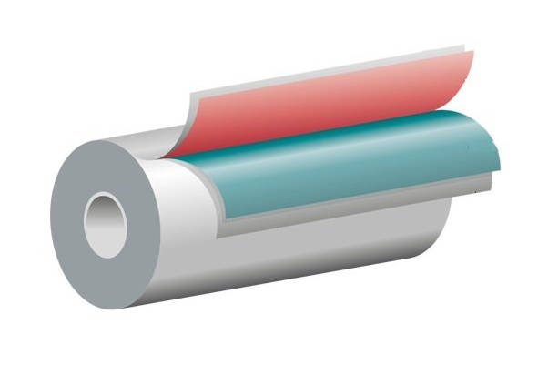
Double-sided OCA sheets rely on an asymmetric release structure: an “easy-release” liner (top carrier) and a “tight-release” liner (bottom base carrier). Calibrating the chemical system and the differential release ratio is essential to keep the adhesive seated on the intended liner during conversion.
Release Coating Chemistry Comparison
- Solvent/Solventless Addition-Cure Silicone: Thermal-cure platinum-catalyzed systems provide flat release profiles, broad peel-force availability (from ultra-light to heavy), and thermal resistance. They represent the primary industry choice for acrylic-based OCAs, provided that platinum poisoning is prevented and silicone migration is controlled.
- Fluorosilicone Coatings: Formulated specifically for silicone-based optical adhesives, which adhere too aggressively to standard polydimethylsiloxane (PDMS) coatings. Fluorosilicone liners provide dependable release against silicone gels, though at a higher material cost.
- Non-Silicone / Modified Polymeric Coatings: Deployed in sensitive optical assemblies where any possibility of siloxane contamination or silicone-induced electrical contact fouling must be avoided. These coatings typically exhibit steeper peel curves at elevated speeds and require tight shelf-life monitoring.
Differential Release Ratio Calibration
For double-sided OCA structures, the peel force of the tight-release liner must be significantly higher than that of the easy-release liner across all production speeds.
| Layer Position | Component | Release Force Specification | Functional Role in Lamination |
|---|---|---|---|
| Top Carrier | Easy-Release Liner | Lowest peel force (e.g., 3–8 g/in) | Stripped first during initial panel or cover-glass placement without disturbing the adhesive layer. |
| Core Layer | OCA Optical Adhesive | Viscoelastic adhesive matrix | Delivers gap-free, optically transparent bonding between optical display substrates. |
| Bottom Carrier | Tight-Release Liner | Controlled higher peel force (e.g., 20–45 g/in) | Anchors the adhesive securely through conversion, slitting, and die-cutting until final bonding. |
If the differential gap is too narrow:
- Peeling the top liner during initial cover-glass lamination can lift the adhesive entirely off the bottom liner (“fly-off”).
- High-speed kiss-cutting causes edge delamination and air pocket formation along the perimeter.
- Unstable web tension causes adhesive stretching, resulting in uneven bond-line thickness.
Engineers generally specify custom release film pairings that maintain a distinct separation in peel force throughout the required storage life, accounting for natural peel force build-up over time.
Cleanroom Manufacturing and Defect Mitigation
Optical clear bonding allows no tolerance for particulate defects. A 30-micron particle invisible on an opaque label liner becomes a conspicuous bright spot or permanent bubble when trapped within an illuminated smartphone or instrument panel stack.
| Defect Phenomenon | Primary Root Cause | Corrective Liner Specification |
|---|---|---|
| Micro-bubbles after autoclave | Surface gels or indentations on PET | Optical-grade low-oligomer substrate |
| Haze increase in display stack | Rough coating or siloxane migration | Low-roughness (Ra) cured coating |
| Pinholes / coating dewetting | Airborne contamination in coating | Class 1,000 / Class 100 cleanroom |
| Particle attraction at peeler | Triboelectric static accumulation | Dual-side antistatic (ESD) coating |
High-yield optical release liners are coated, cured, and slit inside controlled cleanroom environments (typically Class 1,000 to Class 100). This setup prevents airborne fiber contamination, coating voids, and surface scratches during high-tension slitting and rewinding operations.
Step-by-Step Engineering Selection Framework for Display Bonding
Selecting and validating a PET release liner for display bonding involves a structured four-stage evaluation:
| Evaluation Phase | Process Stage | Key Engineering Activities |
|---|---|---|
| Phase 1 | Input Definition | Define adhesive formulation (acrylic/silicone), thickness, line speed, optical haze limits, and thermal exposure. |
| Phase 2 | Laboratory Characterization | Measure 180°/90° peel values across peeling speeds, surface resistivity (ESD), residual adhesion rate, and haze. |
| Phase 3 | Environmental Aging & Thermal Testing | Execute autoclave simulation (heat/pressure) and accelerated aging (e.g., 60°C / 90% RH) to track peel drift. |
| Phase 4 | Pilot Lamination & Die-Cutting Trial | Conduct rotary kiss-cutting and automated vacuum lamination to confirm bubble-free yield and zero edge lift. |
1. Define Boundary Conditions and Interface Requirements
Specify the chemical nature of the adhesive (acrylic vs. silicone), adhesive thickness, lamination peel speed, required liner thickness (e.g., 50 μm, 75 μm, or 100 μm for mechanical rigidity), and maximum allowable haze.
2. Characterize Pilot Samples in the Laboratory
Evaluate initial peel values at 180° and 90° angles across intended process velocities. Measure surface resistivity to confirm static dissipation. Perform solvent rub tests and residual adhesion testing on reference float glass to verify full coating cure.
3. Conduct Environmental Aging Trials
Subject the laminated adhesive-liner composite to accelerated environmental conditions:
- High-temperature/high-humidity storage (e.g., 60°C / 90% RH for 72–168 hours).
- Thermal shock testing simulating shipping conditions.
- Standard autoclave simulation cycles (elevated heat and pressure) to confirm the liner does not wrinkle or transfer release chemistry into the adhesive.
4. Pilot Production and Die-Cutting Verification
Run pilot yardage through automated rotary die-cutting and vacuum lamination equipment. Inspect finished glass-to-display assemblies under optical inspection lamps for micro-bubbles, edge lift, adhesive residue, or dimensional variation.
Key Takeaways
- Liner Quality Dictates Optical Yield: Surface defects, micro-gels, and excessive roughness on a PET release liner transfer directly into OCA, causing permanent optical haze, voids, and micro-bubbles in display panels.
- Peel Differential Prevents Process Failures: Multi-layer OCA assemblies require calibrated differential release ratios between the easy-release and tight-release films to prevent premature adhesive lifting or fly-off during die-cutting.
- Chemical Purity Protects Long-Term Adhesion: Incompletely cured release chemistries lead to siloxane migration, lowering the residual adhesion rate and causing delamination along display edges.
- Cleanroom Processing and ESD Control Are Essential: Optical-grade carrier liners must be coated and slit under cleanroom conditions, with antistatic properties to prevent particle pickup and protect sensitive display electronics.
FAQ
Can standard industrial PET release film be substituted for optical-grade OCA applications?
No. Standard industrial PET liners contain internal slip additives, higher gel counts, and broader coating thickness variations. While suitable for structural tapes or labels, these surface irregularities imprint onto soft optical adhesive, causing unacceptable haze, optical distortion, and air pockets when laminated to cover glass.
How does the autoclave process affect release liner performance?
Autoclaves use high pressure (typically 0.4 to 0.7 MPa) and elevated temperatures (typically 40°C to 60°C) to collapse micro-bubbles within laminated displays. If an OCA remains attached to a carrier during thermal steps, the PET film must exhibit minimal thermal shrinkage to avoid wrinkling, edge curl, or adhesive squeeze-out.
What causes release force to drift over storage time?
Release force drift is typically caused by unreacted chemical components within the release coating slowly reacting with the adhesive, physical interdiffusion between the adhesive matrix and release layer, or the migration of tackifiers and plasticizers. Accelerated aging tests help identify and prevent this drift prior to production runs.
Why is antistatic (ESD) performance required on both sides of an OCA liner?
Adhesive-side antistatic performance prevents high electric field generation during liner stripping at the lamination head, minimizing particle attraction. Backside antistatic treatment prevents static charge accumulation as the film unwinds across conversion rollers, protecting touch sensor ICs and TFT panels from electrostatic damage.