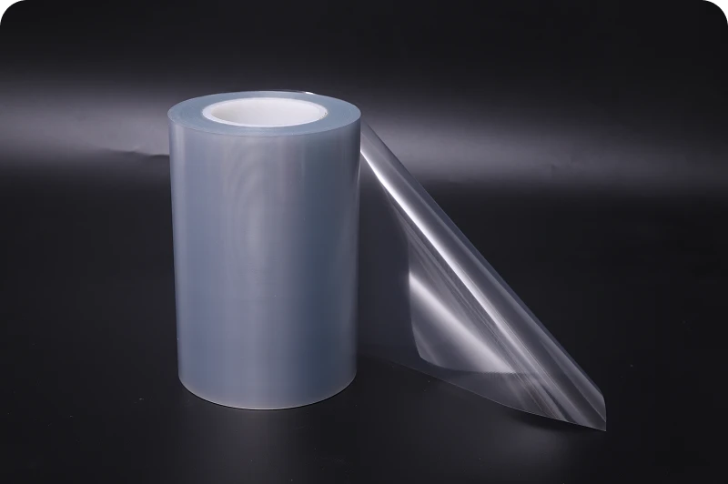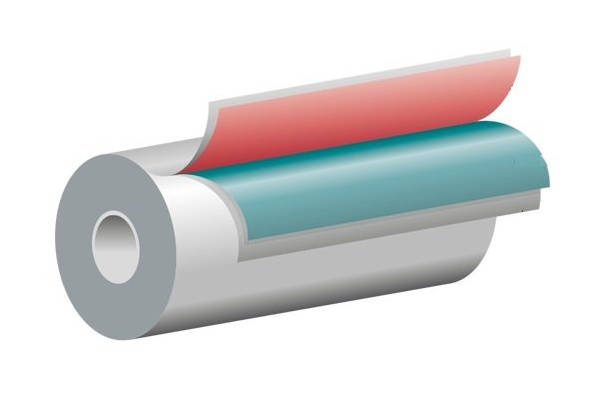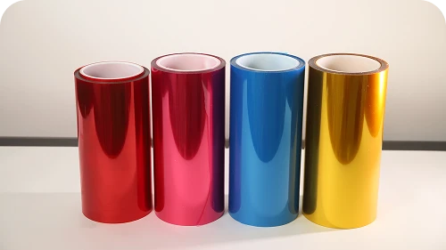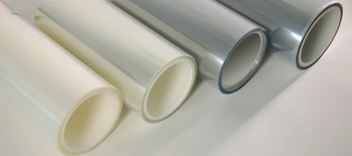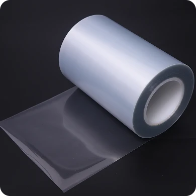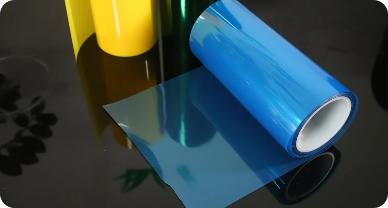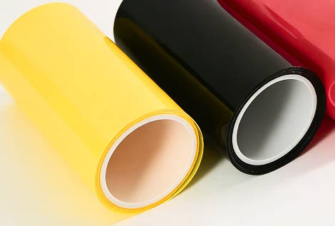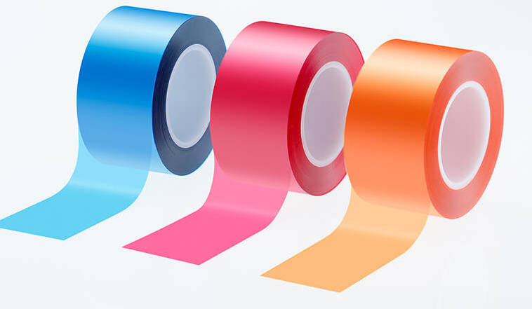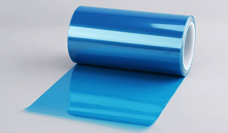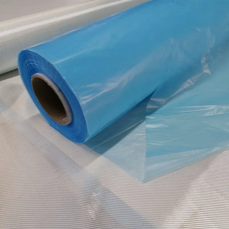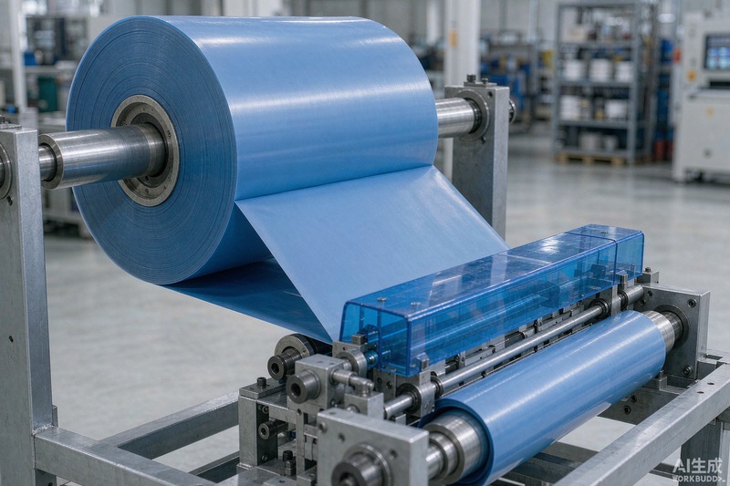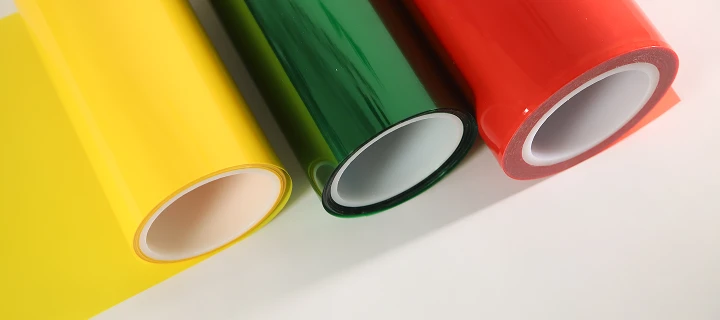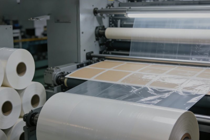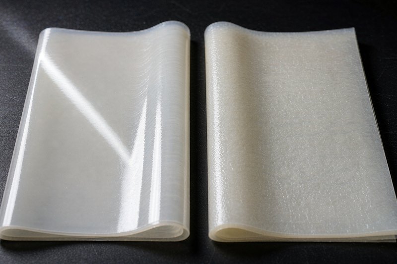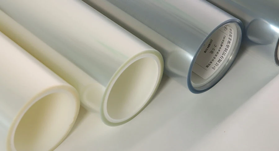
Silicone adhesive tapes require a specialized backing carrier because standard polydimethylsiloxane (PDMS) release coatings fuse chemically to silicone adhesives, resulting in permanent lock-up. A fluorosilicone release film for silicone tape prevents this adhesion failure by using a fluorochemical polymer matrix whose surface energy is significantly lower than silicone pressure-sensitive adhesives (PSAs). Choosing the correct carrier depends on matching release force profiles, thermal stability thresholds, PET base film thickness, and subsequent adhesive strength (SAS) retention.
This guide examines the interfacial chemistry behind fluorosilicone release coatings, details performance across precision die-cutting and thermal processing environments, provides a B2B specification framework, and outlines troubleshooting methods for adhesive delamination and force aging.
Why Standard Release Liners Fail with Silicone Adhesive Tapes
Standard release liners rely primarily on polydimethylsiloxane (PDMS) silicone coatings. While these chemistries provide clean, consistent release from acrylic, natural rubber, and synthetic rubber adhesives, they fail completely when placed in direct contact with silicone pressure-sensitive adhesives.
| System Pairing | Interfacial Mechanism | Boundary Phenomenon | Final Outcome |
|---|---|---|---|
| Standard PDMS Liner + Silicone PSA | Chemical similarity and molecular interdiffusion | Co-crosslinking, mutual wetting, and chain entanglement | Permanent Lock-up (Adhesive failure / liner tearing) |
| Fluorosilicone Liner + Silicone PSA | Incompatible interfacial energy barrier | Ultra-low surface energy, zero mutual wetting, inert boundary | Controlled, Clean Peel (Stable interfacial release) |
The Mechanism of Interfacial Lock-Up
Silicone PSAs share the same fundamental siloxane backbone (Si-O-Si) as standard silicone release coatings. When brought into intimate contact under roll winding pressure or elevated curing temperatures, two failure modes occur:
- Mutual Wetting and Diffusion: Because their solubility parameters and surface energies are nearly identical, the PSA molecules wet and interdiffuse freely across the interface of the release coating.
- Co-crosslinking / Chemical Binding: Unreacted functional groups (such as residual vinyl, hydride, or silanol groups) crosslink across the boundary. Within hours or days of lamination, the adhesive layer fuses permanently to the liner.
- When converting lines attempt to strip the backing, the liner tears, or the silicone adhesive undergoes cohesive failure and transfers entirely to the release carrier. Preventing this failure requires specialized fluorosilicone release film formulations that introduce a chemical barrier incompatible with silicone chemistry.
The Mechanics Behind Fluorosilicone: How It Tames Silicone PSA
Fluorosilicone release agents modify the standard siloxane backbone by substituting selected methyl side groups with perfluoroalkyl segments (such as trifluoropropyl groups). This structural modification dramatically changes the interface dynamics.
Low Surface Energy and Chemical Inertness
Silicone adhesives already exhibit low surface energy (typically around 20 to 22 dynes/cm), which allows them to wet low-energy substrates like polyolefins and powder coatings. To establish differential release against a silicone adhesive, the liner coating must achieve a surface tension well below that of the adhesive itself.
Fluorosilicone networks achieve surface energies typically below 16 dynes/cm. The perfluoroalkyl side chains orient toward the air-coating interface during thermal or UV curing, presenting a dense fluorine shield. This barrier resists wetting by siloxane chains, eliminating interdiffusion and preventing chemical bonding.
Preserving Subsequent Adhesive Strength (SAS)
In high-performance silicone bonding—such as thermal management pads or electronics shielding—the primary concern after unwinding is whether the adhesive retains its specified bonding power.
If a release coating is under-cured, low-molecular-weight silicone fractions or unreacted fluorinated oligomers can migrate into the silicone adhesive layer. This transfer contaminates the bonding surface, drastically lowering its Subsequent Adhesive Strength (SAS). Well-engineered fluorosilicone systems typically target residual adhesive strength retention exceeding 85% to 90%, ensuring that peeling the protective film leaves the silicone PSA fully functional for its end-use bond.
Critical Engineering Roles Across Precision Applications
Selecting the correct release backing depends on the mechanical and thermal demands of downstream converting. Industrial applications demand distinct film attributes beyond basic non-stick properties.
High-Temperature Thermal Processing & SMT Masking
Silicone masking tapes, such as polyimide (PI) silicone tapes used in Surface Mount Technology (SMT) and wave soldering, undergo processing temperatures ranging from 200°C to 260°C.
- Thermal Dimensional Stability: The carrier film—typically biaxially oriented polyethylene terephthalate (BOPET)—must undergo heat stabilization to prevent thermal shrinkage, curl, or edge lifting in baking ovens.
- Release Force Drift Prevention: Extreme heat can accelerate secondary curing at the interface. High-grade fluorosilicone coatings prevent release force “creep” or climbing after prolonged thermal exposure.
Precision Die-Cutting & High-Speed Automated Dispensing
In rotary and flatbed die-cutting for electronics gasketing and automotive battery packs, the release liner functions as a mechanical die base:
- Caliper Uniformity: Inconsistent liner thickness causes cut-through or uneven kiss-cutting where the die blade fails to cut the adhesive cleanly.
- Controlled Delamination: During automated high-speed label dispensing or tape unwinding, the release force must remain smooth and chatter-free to avoid web breaks and feeding errors.
| Application Area | Primary Substrate / Adhesive Type | Key Engineering Challenges | Critical Liner Requirements |
|---|---|---|---|
| SMT & Wave Solder Masking | Polyimide (Kapton) + Silicone PSA | High heat exposure (200°C–260°C); thermal shrinkage risks | Heat-stabilized PET; high-temperature release stability |
| Electronic Thermal Pads | Gap fillers & Thermal Conductive Silicone | Thick, highly conformable, low cohesive strength adhesives | High clarity; calibrated release force to avoid pad deformation |
| EV Battery Pack Gasketing | Silicone Sponge / Foam + Double-sided Tape | Rotary kiss-cutting; high-speed automated robotic pick-and-place | Precise caliper control; anti-static (ESD) surface treatment |
| Industrial Splicing Tapes | PET / Glass Cloth + Heavy Coat-weight Silicone | High peel resistance; long-term shelf storage under roll tension | Heavy release formulation; resistance to release force climb |
How to Select the Right Fluorosilicone Release Film: Key Evaluation Metrics
Specifying a release liner requires balancing mechanical substrate specifications with surface coating properties.
| Evaluation Stage | Core Parameter Focus | Practical Engineering Criteria |
|---|---|---|
| 1. PET Base Caliper | Substrate thickness (25 μm – 75 μm+) | 25–38 μm for flexible rolls; 50 μm standard flatbed; 75 μm+ for rotary kiss-cut stability |
| 2. Release Force Range | 180° peel force calibration | Light (3–10 g/in), Medium (10–30 g/in), Heavy (30–80+ g/in) based on adhesive tack and speed |
| 3. Surface Treatments | Functional layers and ESD control | Single-sided vs. differential release; antistatic topcoats for cleanroom particle control |
| 4. Thermal & SAS Testing | Aging resistance and residual tack | Thermal shrinkage thresholds; post-aging release drift; SAS retention target > 85%–90% |
1. Base Film Thickness (Caliper)
- 25 μm to 38 μm: Used where minimal profile or high flexibility is required, commonly in single-sided silicone tape rolls or manual field application.
- 50 μm (Standard): The industry standard balancing tensile strength, flexural rigidity, and handling efficiency for flatbed die-cutting.
- 75 μm to 100 μm: Essential for high-precision rotary die-cutting lines where blade impression depth must be tightly held without liner puncture.
2. Calibrated Release Force Tiers
Release force is typically verified using 180° peel testing (such as FINAT or FTM standard test methods) against specific silicone adhesive tapes:
- Light Release (Approx. 3 to 10 g/inch): Suitable for delicate, low-tack silicone adhesives or wide-web automated peeling where minimal mechanical drag is vital.
- Medium Release (Approx. 10 to 30 g/inch): The primary operating range for general converting, double-sided silicone tapes, and hand-applied masking products.
- Heavy Release (Approx. 30 to 80+ g/inch): Required for the tight side of differential double-coated tapes or aggressive, thick silicone PSAs to prevent premature pre-dispensing.
(Note: Exact release force values vary based on the specific adhesive formulation, coat weight, and peel speed; specifications should be confirmed via lab trial verification.)
3. Surface Resistivity and Static Control
Polyester film generates significant triboelectric charges during high-speed unwinding. In cleanroom manufacturing and semiconductor assembly, static sparks attract airborne particulate contamination and can damage sensitive electronic components. Specifying an antistatic (ESD) topcoat or incorporating anti-static properties directly into the film prevents static build-up during converting.
For projects requiring specialized substrate thickness or surface treatments, engineers can evaluate custom release film options calibrated to their specific adhesive tack and converting speeds.
Common Failure Modes in Silicone Tape Production and How to Prevent Them
When quality issues emerge on the production floor, evaluating the interaction between the liner and adhesive clarifies whether the root cause is mechanical, chemical, or operational.
| Observed Failure Mode | Probable Root Cause | Corrective & Preventive Action |
|---|---|---|
| Liner Lock-Up (Cannot peel after storage) | Chemical interdiffusion; unreacted siloxanes; non-fluorinated liner used by error. | Verify fluorosilicone chemistry; evaluate curing completeness of adhesive and liner coating. |
| Release Force Creep / Aging Drift | Storage under elevated heat/humidity; residual crosslinkers migrating across the interface. | Store rolls below 25°C and 60% RH; specify thermally stable fluorosilicone coating with low extractables. |
| Adhesive Ghosting / Low SAS After Peeling | Under-cured fluorosilicone release agent transferring to the silicone PSA layer. | Audit liner vendor curing parameters; conduct solvent extraction testing; verify SAS > 85%. |
| Liner Tear During Rotary Die-Cutting | Substrate caliper too thin for die strike depth; improper anvil gap calibration. | Upgrade PET carrier thickness (e.g., from 50 μm to 75 μm); re-calibrate die clearance to prevent base penetration. |
| Pre-dispensing / Tunneling During Unwind | Release force too light relative to tape roll winding tension; air entrapment. | Increase release force tier; adjust web tension profiles on slitting and rewinding equipment. |
Key Takeaways
- Incompatibility Necessity: Silicone pressure-sensitive adhesives cannot use conventional PDMS silicone liners because identical surface energies cause molecular diffusion and permanent chemical lock-up.
- Fluorine Shield Mechanism: Fluorosilicone release coatings lower surface energy below 16 dynes/cm, creating an inert boundary that resists wetting and prevents silicone-to-silicone crosslinking.
- Subsequent Adhesive Strength (SAS): Liner quality is defined not just by how easily it peels, but by how cleanly it releases without leaving migratory oligomers that degrade subsequent bond strength.
- Process-Driven Caliper Selection: Thinner liners (25–38 μm) serve roll-tape applications, while 50–75 μm+ rigid PET backings are necessary to maintain dimensional stability and prevent tear-through during precision rotary die-cutting.
- Storage Stability: Silicone tapes laminated with fluorosilicone liners must be stored away from excessive heat and direct sunlight to prevent release force drift over shelf life.
Frequently Asked Questions (FAQ)
Can non-silicone (acrylic or rubber) adhesives use fluorosilicone release film?
Yes, fluorosilicone liners release exceptionally well from acrylic and rubber adhesives because of their ultra-low surface energy. However, using fluorosilicone for non-silicone adhesives is rarely cost-effective. Standard silicone-coated liners provide stable release for acrylic and rubber systems at a substantially lower cost. Fluorosilicone is typically reserved for silicone PSAs or specialized differential multi-layer tapes.
What is the typical shelf life of a fluorosilicone-coated PET film?
When stored under recommended warehouse conditions (typically 15°C to 25°C and 45% to 60% relative humidity, out of direct sunlight), high-quality fluorosilicone PET liners have a shelf life of approximately 12 months. Beyond this timeframe, rolls should be re-tested for release force stability and surface energy drift before running on production lines.
How does temperature affect the peel force of fluorosilicone release liners?
Peel force generally increases slightly at elevated temperatures as polymer chains become more mobile and adhesive compliance increases. High-grade fluorosilicone coatings designed for industrial tapes minimize this shift, maintaining predictable release characteristics through high-temperature curing and processing cycles.
What is differential release, and why is it used in silicone tape converting?
Differential release refers to double-sided tape constructions where one side of the liner peels away more easily than the other (e.g., an easy-peel side at 10 g/in and a tight-peel side at 40 g/in). This differential ensures that as the tape is unwound, the adhesive stays anchored to the intended carrier layer without tunneling, blistering, or accidental pre-dispensing.