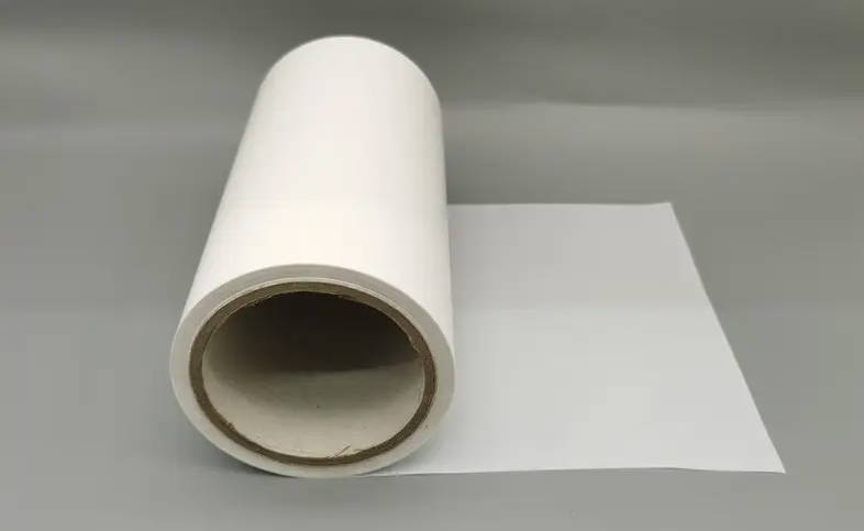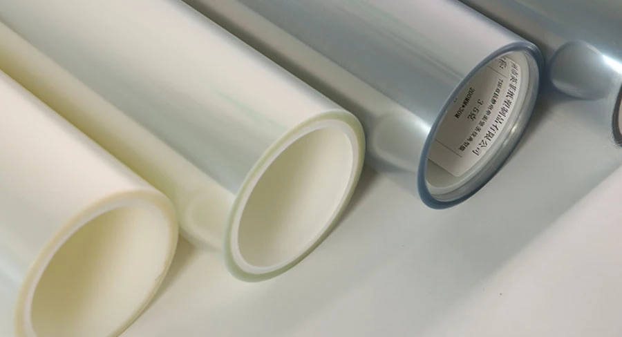
Choosing the right PET release film for OCA (optically clear adhesive) bonding requires balancing peel force differentials, coating stability, cleanroom cleanliness, and electrostatic discharge protection. In touch panels, mobile displays, and automotive screens, standard industrial release liners fail because microscopic surface defects, silicone residue transfer, or uneven peel force cause lamination bubbles, optical haze, or adhesive lifting.
To select the correct carrier liner, process engineers and procurement teams must evaluate adhesive chemistry, peel speed, substrate tension, and post-lamination optical clarity. This guide outlines the core engineering parameters, differential release force ratios, coating chemistries, and qualification workflows required to source reliable precision PET release liner solutions for optical bonding.
The Critical Role of PET Liners in OCA Optical Bonding
An optically clear adhesive transfer tape relies on two release liners to protect its adhesive surfaces before final assembly. Unlike generic packaging or pressure-sensitive tape liners, an optical-grade PET carrier directly shapes the surface morphology of the unbonded adhesive.
| Stack Layer | Functional Description | Key Processing Role |
|---|---|---|
| Upper Liner | Light Release (Easy Peel) | Stripped first during initial lamination to cover lens or sensor. |
| Core Layer | OCA (Optically Clear Adhesive) | Provides refractive index matching and structural bonding. |
| Bottom Liner | Heavy Release (Tight Peel) | Retains adhesive carrier integrity until final display panel bonding. |
When a low-grade liner is removed during automated vacuum or roller lamination:
- Inconsistent release force causes adhesive stretch, leading to thickness variation and optical distortion across the display window.
- Surface orange peel or pinholes transfer directly into the liquid-like acrylic or silicone OCA matrix, forming micro-voids and entrapped bubbles.
- Airborne particulate contamination disrupts the refractive index match between the cover glass and display panel, producing visible black spots or clouding.
Using a liner engineered specifically for optical stack-ups protects the functional surface of the OCA and preserves optical transmission and bonding yield.
Core Engineering Parameters for Optical-Grade PET Release Films
Specifying a PET release film for optical assembly involves mechanical, chemical, and optical tolerances tighter than those of standard electronic assembly films.
| Engineering Parameter | Optical-Grade Target Specification | Standard Industrial Grade Reference | Impact on OCA Lamination |
|---|---|---|---|
| Cleanroom Class | Class 1,000 / Class 100 coating lines (supplier certified) | Class 10,000 to unrated | Eliminates micro-dust embedded at the adhesive-liner interface. |
| Base Film Haze | Low haze / High optical clarity (per TDS) | Standard clarity, uncalibrated | Prevents optical inspection camera errors during auto-alignment. |
| Thickness Uniformity | Tight tolerance across full web width | Standard commercial tolerance | Prevents uneven roller pressure and localized air entrapment. |
| Surface Resistivity (ESD) | Typically 109–1011 Ω/sq (when treated) | >1012 Ω/sq (Insulative) | Prevents electrostatic attraction of airborne debris during high-speed peel. |
| Subsequent Adhesion Rate (ROA) | ≥90% to 95% (application verified) | Often unmeasured or <85% | Verifies minimal release agent migration to preserve final bonding strength. |
Subsequent Adhesion and Silicone Migration
The subsequent adhesion rate measures whether chemical compounds migrate from the release coating into the adhesive layer. When low-molecular-weight silicones or unreacted curing agents detach from the PET carrier and enter the OCA:
- The adhesive’s glass transition temperature (Tg) and cohesive strength shift locally.
- The final peel adhesion to cover glass or ITO sensor film drops, increasing the risk of edge peeling or delamination under environmental heat and humidity.
- Optical haze increases, altering display contrast and ambient light transmission.
High-grade optical liners use cross-linked cured formulations to lock the release system to the polyester base film and prevent chemical migration.
Release Force Architecture: Designing the Differential Ratio for Dual-Sided OCA
Double-sided OCA sheets require a two-stage peeling process using a light liner (easy release) and a heavy liner (tight release). Balancing this differential ratio prevents the adhesive from transferring to the wrong liner during high-speed die-cutting or inline assembly.
| Assembly Step | Target Liner Action | Adhesive Behavior | Process Outcome |
|---|---|---|---|
| Step 1 | Peel Light Liner (Low Force) | Adhesive adheres firmly to Heavy Liner | Initial lamination to cover glass or ITO film |
| Step 2 | Peel Heavy Liner (High Force) | Adhesive transfers completely to target glass | Final optical assembly to display module |
Peel Force Differential Guidelines
The Differential Ratio: The peel force of the heavy liner should consistently exceed that of the light liner across your operational peeling speeds. A ratio between 1:2 and 1:4 is standard for automated module lines, depending on adhesive tack and thickness.
Peel Speed Sensitivity: Release force increases as peeling speed accelerates. If the light liner’s release chemistry exhibits high velocity sensitivity, high-speed robotic peelers can cause the light side to grip tighter than the heavy side, causing adhesive lifting or tunneling (premature delamination between the film and adhesive core).
Peeling Angle Control: Automated peel tests and machine setups typically run at 90° or 180°. The chosen release force pair must remain stable under the actual mechanical angle used by the lamination machinery.
When designing custom laminates, converting engineers source custom differential release film options calibrated to specific adhesive tack levels and processing speeds.
Coating Chemistry: Silicone vs. Fluorosilicone vs. Non-Silicone
The chemical foundation of the release layer determines compatibility with the adhesive and downstream optical reliability.
| Adhesive Chemistry | Recommended Liner Coating | Primary Performance Advantage | Application Risk / Limitation |
|---|---|---|---|
| Acrylic OCA | Thermal Cure / UV Cure Silicone | Low, stable peel force and high force consistency | Incompatible with silicone-based optical adhesives |
| Silicone OCA | Fluorosilicone Release System | Resists wetting and bonding by silicone adhesives | Higher raw material cost; requires uniform coating controls |
| Sensitive Optical Sensors | Non-Silicone (Olefin / Acrylate) | Eliminates silicone migration and sensor poisoning | Higher minimum release force; sensitive to storage temperature |
1. Thermal Cure and UV Cure Silicone
Typical Use: Standard acrylic-based OCA tapes for mobile phones, monitors, and consumer displays.
Characteristics: Offers low, stable release values and tight force tolerances. Thermal systems provide stable curing, while UV systems provide a dense cross-linked surface that reduces silicone transfer.
Caution: Incompatible with silicone-based optical adhesives due to cross-affinity that causes irreversible bonding.
2. Fluorosilicone Release Liners
Typical Use: Silicone-based optical adhesives, often specified for wide-temperature automotive cockpit displays, military-grade screens, or curved flexible OLED modules.
Characteristics: The fluorinated polymer backbone resists wetting and bonding by silicone adhesives, ensuring smooth release where standard silicone liners lock permanently.
Caution: Higher raw material cost requires verification of cleanroom line compatibility and coating thickness uniformity.
3. Non-Silicone Liners
Typical Use: Highly sensitive optical assemblies where any silicone vapor or residue risks sensor poisoning, contact degradation, or coating defects in secondary vacuum deposition processes.
Characteristics: Uses specialized non-silicone polymers (such as functionalized polyolefins or acrylates) to achieve release without silicone migration risk.
Caution: Delivers a higher minimum peel force than silicone coatings and typically requires tighter storage temperature controls.
Step-by-Step Selection Workflow for Module Manufacturers and Die-Cutters
Sourcing the wrong liner creates production line failures, including machine jams, edge tear, and high scrap rates. Precision converters and module assemblers should evaluate PET liners using a structured 5-step engineering process:
- Define Adhesive Chemistry and Thickness
Determine whether the adhesive core is standard acrylic, modified acrylic, or silicone. Thicker adhesives (e.g., 175 µm to 250 µm) conform more tightly to release surfaces and generate higher peel resistance than thinner layers (e.g., 25 µm to 50 µm). - Establish Machine Speed, Tension, and Peeling Angle
Calibrate peel force requirements to line speed rather than static laboratory bench tests. Select a PET base film thickness (commonly 50 µm, 75 µm, or 100 µm) that provides enough tensile modulus to prevent stretching or web break under die-cutting tension. - Specify Cleanliness and Antistatic Requirements
Review environmental controls on the coating line. When running automated peel-and-place lines, specify an antistatic (ESD) coating on the non-release or release-treated face to prevent static field generation and particle attraction. - Conduct Thermal Aging and Peel Stability Trials
Condition small laminate samples under accelerated aging (e.g., 60 °C / 90% RH for 72 to 168 hours). Measure the peel force delta to ensure the liner does not lock up over storage, and confirm that subsequent adhesion (ROA) remains above operational limits. - Audit Inline Die-Cutting and Lamination Yield
Inspect die-cut edges using precision die-cutting PET release liners to ensure clean fracture without tearing, adhesive stringing, or delamination. Track optical transmission and bubble counts under an optical microscope after autoclave degassing.
Troubleshooting Common Optical Bonding Failures
Liner defects often appear as adhesive or lamination failures during pilot runs. Use this matrix to identify root causes related to the release liner.
| Defect Symptom | Process Observation | Potential Release Film Cause | Corrective Action |
|---|---|---|---|
| Lamination Bubbles After Autoclave | Small voids reappear hours after autoclave cycle. | Surface orange peel, pinholes, or uneven coating thickness on the PET liner. | Switch to an optical-grade liner with verified coating smoothness and tighter thickness uniformity. |
| Adhesive Lifting / Tunneling | Adhesive lifts off the heavy liner when the light liner is stripped. | Insufficient peel force differential, or light liner peel force spiked at high speed. | Increase the differential ratio (e.g., from 1:2 to 1:3) or select a velocity-stable release chemistry. |
| Micro-Particle Contamination | Black specks or fibers visible under the cover glass. | Unrated production cleanroom, or insulative PET generating static attraction. | Require Class 1,000 cleanroom manufacturing with inline electrostatic dissipation (ESD) treatment. |
| Reduced Adhesion Over Time | OCA lifts from cover glass weeks after module assembly. | Free silicone migration from liner coating contaminating the adhesive surface. | Verify Subsequent Adhesion Rate (≥90%) and switch to a cured, low-migration silicone system. |
| Web Break During Die-Cutting | PET carrier snaps along high-speed slitting or punch stations. | Base film too thin or lacking required tensile modulus. | Increase base PET thickness (e.g., from 50 µm to 75 µm or 100 µm) with balanced MD/TD orientation. |
Procurement and Supplier Evaluation Checklist
Before finalizing an order with an optical film manufacturer, engineering and sourcing teams should request and confirm the following technical data:
- Production Cleanroom Certification: Verify that the coating and slitting lines operate within controlled cleanroom environments (e.g., Class 1,000 or Class 100) with continuous automated optical inspection (AOI) to flag gels, fish eyes, and pinholes.
- Standardized Release Force Test Data: Ensure peel values are validated under recognized industrial standards (such as FINAT FTM 1, FTM 3, or ASTM D3330) specifying test tape, peel speed, dwell time, and temperature.
- Custom Slitting and Edge Quality: Micro-cracks along slit roll edges create tear propagation points during roll-to-roll automated lamination. Suppliers must use dedicated razor or shear slitting designed for optical films.
- Packaging and Core Integrity: Cleanroom-compatible plastic cores (ABS or dust-free PVC) and vacuum-sealed, suspended packaging prevent roll flat-spotting and particulate contamination during sea or air transit.
Evaluating these parameters alongside technical data sheets from specialized PET release film manufacturers ensures production line stability and reduces scrap rates in sensitive optical bonding assemblies.
Key Takeaways
- Differentiate Clear from Industrial: Standard industrial release films carry surface roughness and chemical residues that compromise optical stack-ups. Only optical-grade cleanroom-manufactured PET liners should protect OCA.
- Establish a Stable Differential Ratio: Maintain a release force spread between 1:2 and 1:4 across operational peeling speeds to prevent adhesive lifting, tunneling, and automated equipment jams.
- Prevent Silicone Migration: Demand high subsequent adhesion rates (ROA ≥90%) to maintain bond integrity between the optical clear adhesive, cover lens, and display panel.
- Match Coating to Adhesive Chemistry: Use thermal or UV silicone for acrylic adhesives, fluorosilicone for silicone adhesives, and non-silicone liners for ultra-sensitive optical or sensor surfaces.
- Control Static Charge: Integrate antistatic (ESD) surface treatments to eliminate particle contamination during high-speed liner removal.
Frequently Asked Questions (FAQ)
What is the difference between an optical-grade PET release film and a standard electronics release film?
Optical-grade PET release films are manufactured and slit in Class 1,000 or Class 100 cleanrooms using optical-clarity base resins. They undergo inline optical inspection to eliminate gels, dust, and pinholes. They also feature tightly controlled release coatings that prevent chemical migration, ensuring the refractive index, haze, and bonding strength of the OCA remain intact.
Why does the differential release ratio matter in dual-sided OCA manufacturing?
A dual-sided OCA requires one liner to release easily while the other holds the adhesive firmly against its carrier. If the differential ratio is too narrow, or if dynamic peel force spikes at high peeling speeds, the adhesive can detach from the wrong carrier, tearing the adhesive layer and shutting down automated production lines.
How does release force aging affect OCA storage?
Release force naturally builds over time due to adhesive wet-out and interfacial chemical relaxation. High ambient heat and humidity accelerate this build-up. Optical films must undergo accelerated aging tests (e.g., 60 °C / 90% RH) to confirm that the release force remains within operational tolerances throughout the product’s shelf life.
Can a silicone-coated PET release film be used with silicone-based OCA?
No. Silicone release agents bond chemically with silicone-based optical adhesives, preventing separation. Silicone OCAs require fluorosilicone-coated release liners, which provide the surface energy differential needed to release cleanly without tearing the adhesive.
What base film thickness is recommended for OCA optical bonding?
Most optical clear adhesives use 50 µm, 75 µm, or 100 µm PET release films. Thinner films (e.g., 50 µm) offer flexibility for light-side liners and manual peels, while thicker films (75 µm to 100 µm) provide the dimensional stability, tensile modulus, and stiffness needed for precision die-cutting and high-speed automated roll-to-panel lamination.