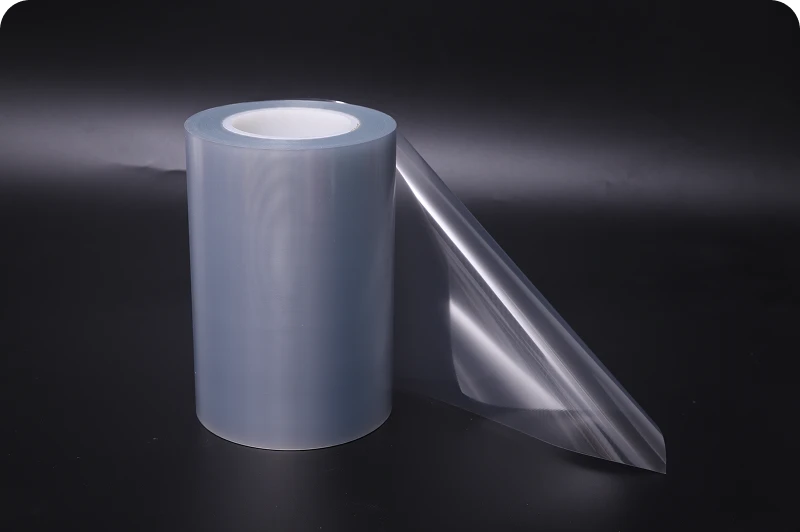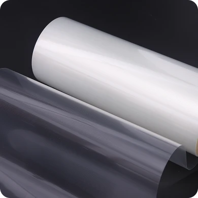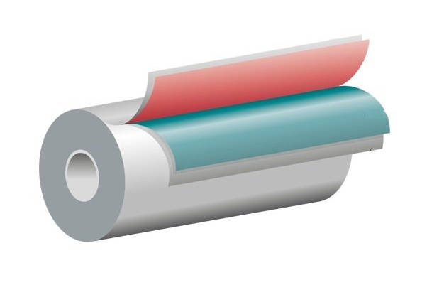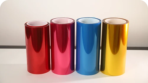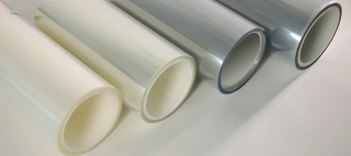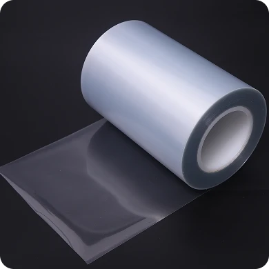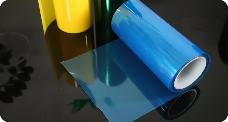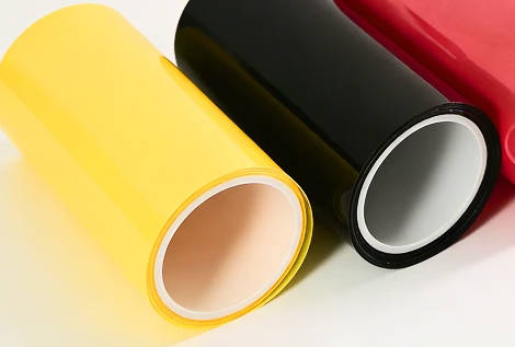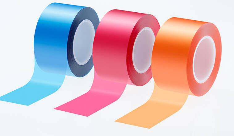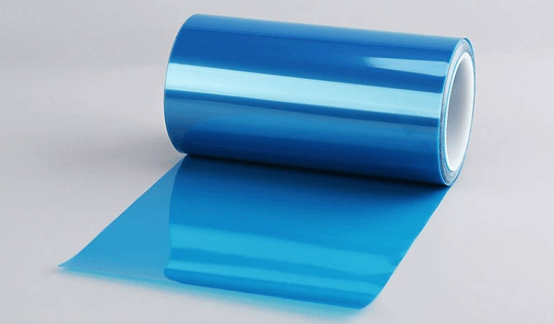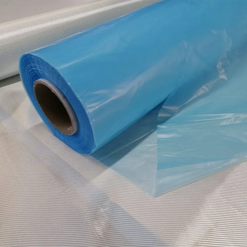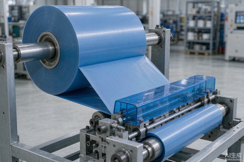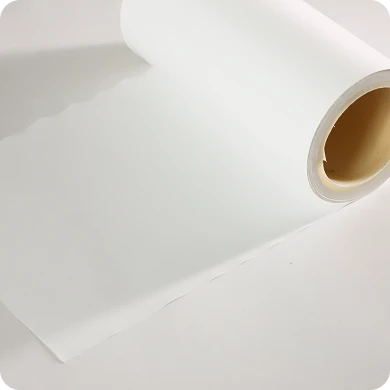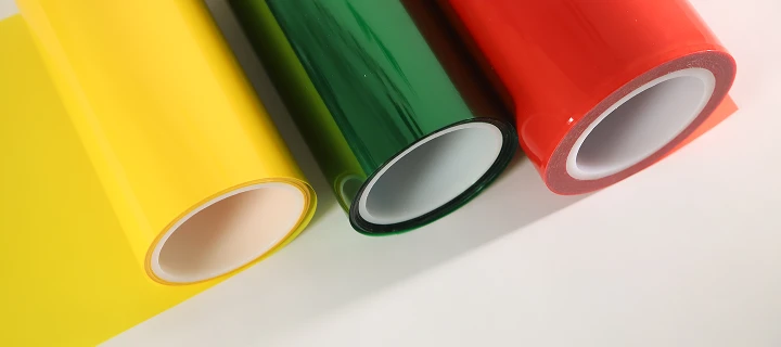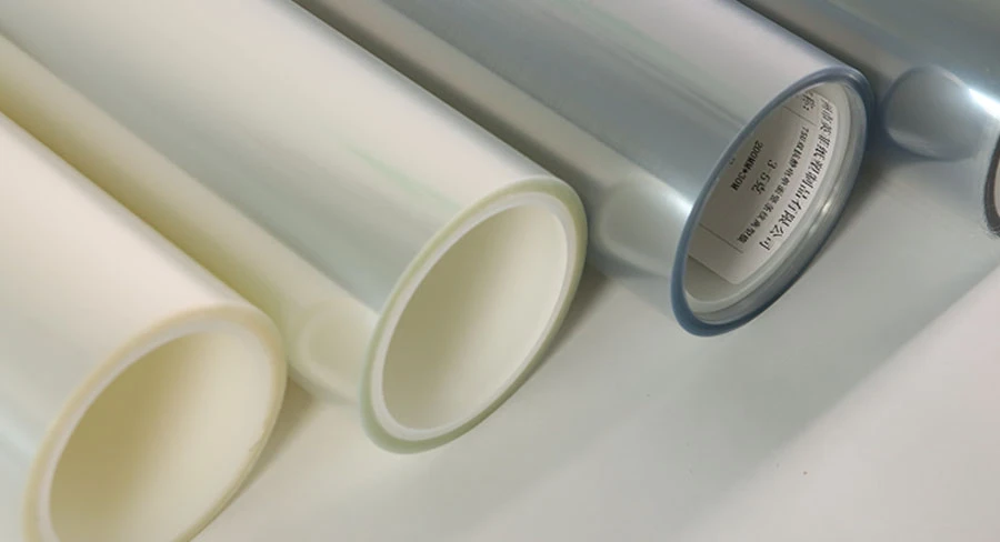
Silicone pressure-sensitive adhesives (PSAs) deliver exceptional thermal endurance, chemical inertness, and electrical insulation across demanding industrial assemblies. However, their unique polymer chemistry creates a severe manufacturing dilemma: they fuse irreversibly to standard polydimethylsiloxane (PDMS) release coatings. A fluorosilicone release film provides the critical boundary layer that resolves this compatibility conflict. By incorporating fluorine-modified functional groups into a silicone polymer backbone, these engineered liners establish an ultra-low surface energy barrier that permits clean, uniform separation from silicone adhesive systems without degrading bonding performance.
Selecting the proper fluorosilicone coated liner requires balancing interfacial surface tension, cure integrity, and dimensional stability under thermal stress. This guide breaks down the chemical mechanisms preventing adhesive lockup, evaluates release force stability across converting stages, and outlines an engineering framework for specifying differential liners for high-temperature masking, thermal management, and precision die-cutting applications.
1. The Engineering Dilemma: Why Silicone Adhesives Reject Conventional Release Liners
Silicone pressure-sensitive adhesives rely on a flexible polydimethylsiloxane backbone cross-linked into an elastomeric network. While this structure yields compliance and wetting capability on low-surface-energy substrates, it also creates an inherent thermodynamic affinity for identical chemical structures.
| Boundary Layer | Chemical Characteristic | Interfacial Interaction | Failure Outcome |
|---|---|---|---|
| Silicone PSA Layer | Flexible siloxane chains with high cohesive affinity | Interfacial diffusion into identical polymer network | Permanent Fusion (“Adhesive Lockup”); release liner cannot separate |
| Standard PDMS Liner | Unmodified siloxane backbone (matched surface tension) | Secondary cross-linking and chain entanglement during cure |
When tape coaters apply a silicone adhesive formulation onto standard silicone-coated paper or poly(ethylene terephthalate) (PET) liners, the mobile siloxane chains of the wet adhesive interdiffuse with the cured siloxane network of the release coating. Under elevated thermal curing or extended roll storage, secondary cross-linking reactions occur across the interface. The resulting phenomenon—known in converting as adhesive lockup—welds the adhesive permanently to the carrier film.
In high-speed rotary die-cutting and automated pick-and-place lines, adhesive lockup causes:
- Delamination of the functional tape backing rather than release along the liner interface.
- Web breaks and catastrophic blade fouling from unreleased adhesive residue.
- Irreversible mechanical distortion of precision components, particularly thin polyimide (PI) flex circuits and thermal interface pads.
To maintain production continuity, silicone adhesive systems require an engineered release surface that repels siloxane chains during thermal curing, roll winding, and accelerated storage aging.
2. Interfacial Chemistry: How Fluorosilicone Coatings Prevent Silicone-on-Silicone Fusion
Fluorosilicone release chemistry modifies standard siloxane backbones by substituting specific methyl (-CH3) side chains with perfluoroalkyl or trifluoropropyl (-CH2CH2CF3) moieties. This substitution fundamentally alters interfacial thermodynamics in three distinct ways:
Surface Energy Depletion
Standard cured polydimethylsiloxane coatings exhibit critical surface tensions between 20 and 22 mN/m. Silicone PSAs exhibit surface energies within an almost identical band (approx. 20–24 mN/m), facilitating mutual spontaneous wetting and chain entanglement. Incorporating fluorinated functional groups drives the cured solid surface energy down below 16–18 mN/m. Because the surface tension of the fluorosilicone coating is lower than the cohesive surface energy of the silicone PSA, the adhesive cannot fully wet or penetrate the release network.
Steric Hindrance and Incompatibility
The electronegative fluorine atoms form an electron-dense sheath around the polymer backbone. This creates significant steric hindrance, preventing silicone PSA macromolecular chains from approaching the release surface close enough to establish van der Waals bonding or secondary hydrogen bonding networks.
| Interface Component | Molecular Structure / Group | Interfacial Role | Boundary Effect |
|---|---|---|---|
| Fluorosilicone Coating | Fluoroalkyl sheath (-CH2CH2CF3 groups) | Ultra-low surface energy barrier; electron-dense steric shield | Chemically repellent release interface |
| Silicone PSA Layer | Standard dimethylsiloxane units (-Si(CH3)2O-) | Blocked from wetting or interdiffusing into release layer | Clean peel without chain entanglement |
Preservation of Subsequent Adhesion Strength (SAS)
A major risk when peeling release liners is the migration of unreacted oligomers or cross-linking agents from the release surface into the adhesive mass. If low-molecular-weight siloxanes transfer into the silicone PSA, they create a weak boundary layer, permanently degrading the adhesive’s subsequent adhesion strength.
Fully cured fluorosilicone systems designed for specialized industrial release film series utilize platinum-catalyzed addition curing mechanisms to achieve dense network cross-linking. This minimizes extractable fractions, ensuring that when the tape is pulled from the liner, the adhesive retains its target tack, shear strength, and peel adhesion against the final bonding substrate.
3. Technical Performance Comparison: Fluorosilicone vs. Standard Liners for Silicone Adhesives
Selecting liner substrates for silicone tape conversion requires assessing chemical inertness, release profile consistency, and thermal response.
| Performance Metric | Standard Silicone Liner (PDMS) | Non-Silicone Liner (Fluoropolymer/Olefin) | Fluorosilicone Coated Liner |
|---|---|---|---|
| Compatibility with Silicone PSAs | Incompatible; causes permanent fusion and lockup | Marginal; inconsistent wetting and pinholes | Optimal; controlled, reliable release interface |
| Release Force Uniformity | Unusable (peel force exceeds substrate tensile limit) | High initial peel; severe force spikes during unwinding | Smooth, predictable release curves across varied peel speeds |
| Thermal Resistance | Up to 180°C (thermal failure at adhesive boundary) | Limited by polyolefin melting points (often <120°C) | Broad tolerance matching PET carriers (stable through 150°C–200°C cure cycles) |
| Subsequent Adhesion Retention (SAS) | N/A (cannot separate cleanly) | Variable; low-energy waxes can migrate to the adhesive face | Exceptionally high retention (minimal chemical migration when fully cured) |
| Rotary Die-Cutting Performance | Causes blade wrap-up and severe web tearing | Prone to tear, edge burs, or liner stretching | Exceptional dimensional stability on optical-grade biaxially-oriented PET |
| Relative Material Cost | Baseline economy | Moderate to high | Premium engineering grade |
While pure fluoropolymer films (such as PTFE or ETFE) provide native non-stick properties, their poor dimensional stability, mechanical stretch under web tension, and high raw material costs limit their viability in precision die-cutting. A fluorosilicone formulation coated onto durable PET-based release films delivers the mechanical rigidity and flatness of polyester combined with the release chemistry required for silicone adhesives.
4. Critical Engineering Parameters to Control in Die-Cutting and Converting
During precision converting—including high-speed slitting, kiss-cutting, and multi-layer laminating—converting engineers must monitor four core physical and interfacial specifications to prevent downstream failure.
| Engineering Parameter | Converting Sensitivity | Primary Risk | Quality Verification Method |
|---|---|---|---|
| 1. Release Force Profiles | Peeling velocity & take-off angle dynamics | Pre-dispensing or matrix tearing during high-speed stripping | FINAT / ASTM 180° peel testing at designated line speeds |
| 2. Subsequent Adhesion Rate (SAS) | Residual chemical purity on adhesive face | Loss of bonding tack and shear performance on end-use parts | Lab testing of peeled tape vs. pristine control samples |
| 3. Base Substrate Flatness & Caliper | Rotary die depth accuracy during kiss-cutting | Liner cut-through or incomplete adhesive boundary shearing | Optical micrometer profiling across full cross-web width |
| 4. Thermal Shrinkage Stability | Web tension control through high-temp ovens | Thermal curling, puckering, and adhesive thickness distortion | Pre-shrunk, heat-stabilized biaxially-oriented PET validation |
1. Release Force Profiles and Speed Sensitivity
Release force is not static; it changes dynamically with peel velocity and peel angle (typically evaluated at 180° or 90° ASTM D3330 / FINAT FTM 1 test methods). Converters must specify whether the liner is designated for manual peel, continuous slitting, or high-speed pick-and-place lines. A liner that releases smoothly at 300 mm/min may exhibit significant force escalation at 10 m/min if the fluorosilicone polymer architecture possesses high viscoelastic dampening. Target release force ranges (e.g., ultra-light 5–15 g/25mm vs. medium 30–60 g/25mm) must be matched directly to the tack of the silicone adhesive.
2. Subsequent Adhesion Rate (SAS) Verification
The subsequent adhesion rate indicates the percentage of bonding capacity retained by the silicone adhesive after contact with and removal from the release liner:
SAS (%) = (Peel Strength of Tape After Liner Contact / Peel Strength of Fresh Tape) × 100
A reduction in SAS indicates that unreacted fluorinated silicone oligomers have transferred onto the tape surface, acting as a contaminant. For high-reliability electronic assemblies, converters should verify that the cured liner meets application-specific SAS requirements based on batch test data sheets (TDS) rather than generic assumptions.
3. Base PET Caliper Uniformity and Optical Flatness
In precision kiss-cutting operations, the cutting die must pierce through the backing material and the silicone adhesive layer, stopping precisely at the boundary of the release liner without cutting the polyester carrier. Any thickness variation across the web causes the die to either score the release film (leading to web breakage during automated application) or fail to cut cleanly through the adhesive. Utilizing optical-grade precision fluorosilicone release film grades ensures tight thickness tolerances (often within tight single-digit percentage variations) and avoids visual pinholes or silicone coating mottle.
4. Thermal Shrinkage and Dimensional Stability
Silicone adhesive tapes often require high-temperature curing ovens (130°C to 180°C) to drive off solvents and activate cross-linking catalysts. Standard commercial polyester films shrink non-uniformly under these conditions, causing web curling, edge buckling, and uneven tension. Converting lines handling high-temperature silicone chemistry require heat-stabilized, biaxially-oriented PET bases to maintain dimensional flatness and prevent adhesive pooling.
5. Application Matrix: Matching Fluorosilicone Release Films with Silicone-Based Products
Silicone adhesives are engineered into varied industrial formats, each requiring distinct mechanical backing support and release force profiles.
| Application Sector | Typical Product Construction | Release Force Profile & Demands | Engineering Considerations |
|---|---|---|---|
| High-Temp Masking & Powder Coating | Polyimide (Kapton) or glass cloth backing + silicone PSA | Moderate release force; heat resistance to 200°C+ | Low triboelectric charging during high-speed peel; clean residue-free removal |
| Thermal Interface Materials (TIM) | Fiberglass carrier or unsupported soft silicone gel | Ultra-light peel force; zero plasticizer/silicone oil transfer | Must release without stretching or tearing fragile, compliant thermal gap pads |
| Optoelectronics & Display Assembly | Optical-grade clear PET film + silicone gel/PSA | Calibrated tight release force; strict optical cleanliness | Anti-static (ESD) back-coating; complete absence of gel defects and pinholes |
High-Temperature Masking and Polyimide (Kapton) Tapes
- Operating Conditions: Wave soldering, reflow soldering, and powder coating lines operating between 180°C and 260°C.
- Liner Demands: The fluorosilicone liner protects the masking tape during roll storage and slit rewinding. It must peel smoothly without inducing static discharges that can damage sensitive semiconductor components mounted nearby.
Thermal Interface Materials (Silicone TIM Pads and Gap Fillers)
- Operating Conditions: Heat dissipation between microprocessors, automotive power electronics, and heat sinks.
- Liner Demands: Thermal pads often feature soft, highly compliant silicone gel surfaces with low mechanical integrity. If the release force of the liner is too high, peeling the liner tears or stretches the thermal pad. An ultra-light fluorosilicone release liner allows stress-free removal on assembly lines without transferring oils that degrade thermal impedance.
Optoelectronic Surface Protection and Transfer Tapes
- Operating Conditions: Optical component fabrication, display stack-up assembly, and cleanroom environments.
- Liner Demands: Optical-grade PET carriers featuring cured fluorosilicone coatings must adhere to rigorous cleanliness protocols. These applications require minimal haze, total absence of visual gel defects (fish eyes), and anti-static (ESD) surface treatments to eliminate airborne dust attraction during die-cutting.
6. Selection and Sourcing Decision Framework for Tape Manufacturers and Converters
Specifying the correct liner requires systematically evaluating processing variables. When requesting a quotation or custom formulation, engineers should follow a structured decision workflow:
| Stage | Engineering Action Item | Core Variables to Specify | Decision Objective |
|---|---|---|---|
| Step 1 | Define Silicone Adhesive Chemistry | Addition-cured (Pt-catalyzed) vs. Peroxide-cured | Prevent catalyst poisoning and chemical attack on the release layer |
| Step 2 | Establish Converting Mechanics | Peel velocity, peel angle (90° vs. 180°), web width | Match release force profile to prevent web tear or premature release |
| Step 3 | Configure Differential Release Systems | Easy-release side vs. Tight-release side values | Ensure predictable release order on double-sided transfer rolls |
| Step 4 | Validate Environmental Durability | Heat aging (60°C–70°C), elevated RH (85%+), soak time | Prevent release force escalation and adhesive lockup during transit |
Step 1: Define Adhesive Chemistry and Curing Mechanism
Determine whether the silicone adhesive is an addition-cure system (platinum-catalyzed) or a peroxide-cured system. Platinum-cured systems can be susceptible to catalyst poisoning from trace amine, sulfur, or tin compounds present in unwashed base liners, while peroxide systems generate acidic by-products that require neutral release chemistries.
Step 2: Establish Converting Mechanics and Peel Conditions
Detail the downstream converting method:
- High-Speed Rotary Die-Cutting: Requires stiffer, thicker PET backings (typically 50 μm to 75 μm) with medium release force to prevent matrix pre-lifting.
- Manual Field Application: Requires light to ultra-light release force to allow rapid separation by technicians without edge picking.
Step 3: Configure Differential Double-Sided Systems
Double-sided silicone transfer tapes require differential release properties. If both sides of a tape utilize identical release forces, unrolling the finished tape will cause unpredictable splitting and web jams. Tape engineers must specify a calibrated differential release ratio (e.g., an easy-release side at 10–20 g/25mm paired with a tight-release side at 40–70 g/25mm) to ensure the adhesive consistently clings to the intended carrier during roll unwinding.
Step 4: Validate via Accelerated Environmental Aging
Never qualify a fluorosilicone liner based solely on room-temperature peel tests at day zero. Accelerated environmental testing—such as exposing laminated adhesive-and-liner samples to 60°C to 70°C at 80% to 90% relative humidity for 7 to 14 days—is critical to verify that the release force remains flat and that chemical migration does not compromise bonding integrity over the product’s shelf life.
When defining project parameters, engineers can review custom release film specifications to ensure carrier thickness, optical clarity, and release profiles match their converting envelope.
Key Takeaways
- Chemical Incompatibility Solved: Standard silicone release liners fuse irreversibly to silicone PSAs due to identical chemical structures. Fluorosilicone coatings resolve this issue through low surface tension (below 18 mN/m) and electron-dense fluorine atom shielding that blocks interfacial cross-linking.
- Preservation of Bond Performance: Properly formulated, fully cured fluorosilicone systems prevent small-molecule siloxane migration, maintaining high subsequent adhesion strength (SAS) on downstream substrates.
- Converting Control: Precise kiss-cutting and slitting require optical-grade biaxially-oriented PET carriers that deliver strict caliper tolerances, preventing liner cut-through and web breaks.
- Differential Calibration: Dual-sided silicone tape systems require engineered differential release force ratios to guarantee predictable peel sequences during automated unrolling and placement.
- Validation Under Thermal Stress: Accelerated aging tests combining elevated temperature and humidity are necessary to ensure release force stability before commercial-scale manufacturing runs.
Technical FAQ
Can non-fluorinated release films ever be used with silicone adhesives?
Non-fluorinated, non-silicone liners (such as pure untreated polypropylene, high-density polyethylene, or waxed paper) can separate mechanically from low-tack silicone formulations in limited circumstances. However, they lack the thermal endurance required for standard silicone curing ovens (130°C–180°C) and provide inconsistent release forces across high-speed webs. Fluorosilicone coated films remain the standard for high-temperature and high-precision applications.
What is the typical Subsequent Adhesion Rate (SAS) for a qualified fluorosilicone release film?
A production-grade fluorosilicone release film typically maintains a subsequent adhesion rate of at least 85% to 90% when evaluated against qualified silicone test tapes. The exact threshold depends on the adhesive formulation, coat weight, and curing profile, and should be verified directly with the supplier’s technical data sheets and internal peel retention tests.
How does ambient temperature variation affect the release force of fluorosilicone liners?
Because fluorosilicone coatings possess low glass transition temperatures (Tg), their surface energy remains stable across standard operating envelopes. However, extreme heat and humidity during transit or storage can accelerate adhesive relaxation and migration if the coating contains uncured cross-linkers. Qualifying liners via accelerated aging tests (e.g., 65°C / 85% RH) ensures consistent performance across diverse storage climates.
How can converters prevent static buildup when peeling fluorosilicone liners from silicone tapes?
Peeling two non-conductive polymeric films (PET-supported fluorosilicone and silicone adhesive) generates high triboelectric static charges. Converters eliminate static-induced pinholes and dust contamination by specifying release films with specialized antistatic (ESD) surface coatings applied to the back of the PET film or by installing active ionizing blowers directly over the peel and lamination nips.