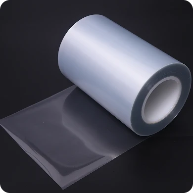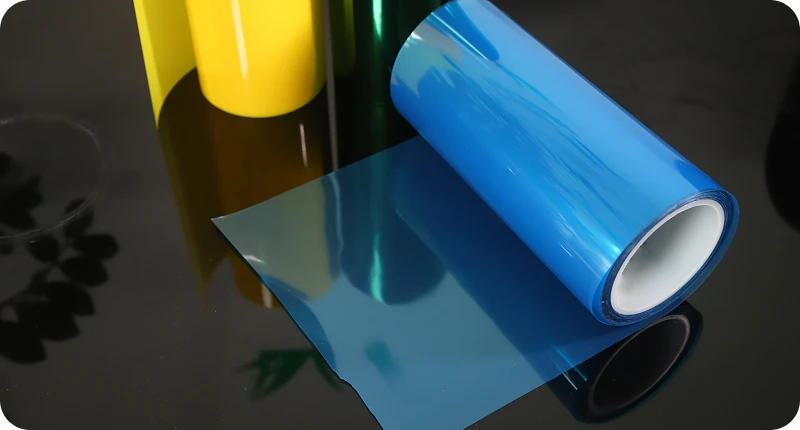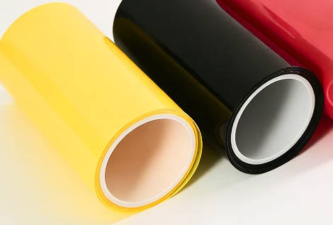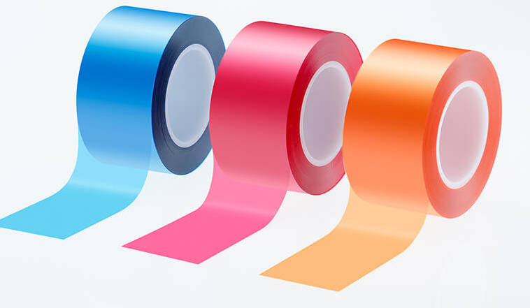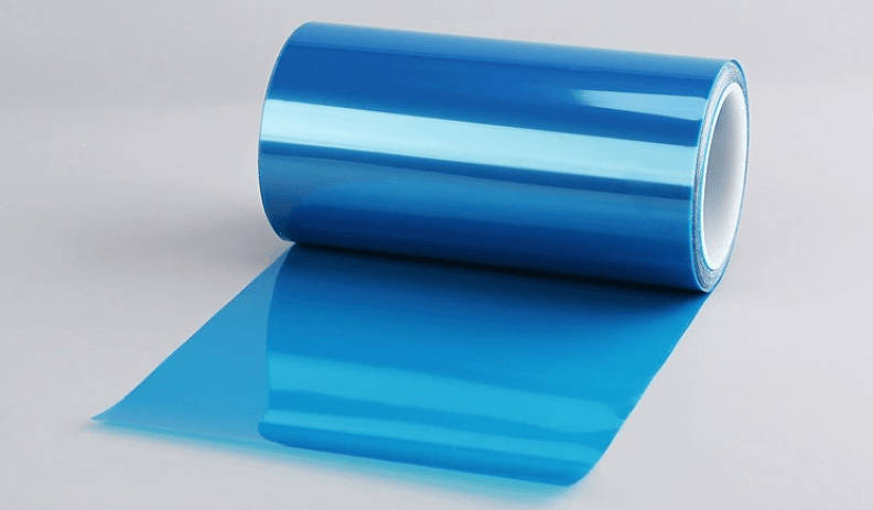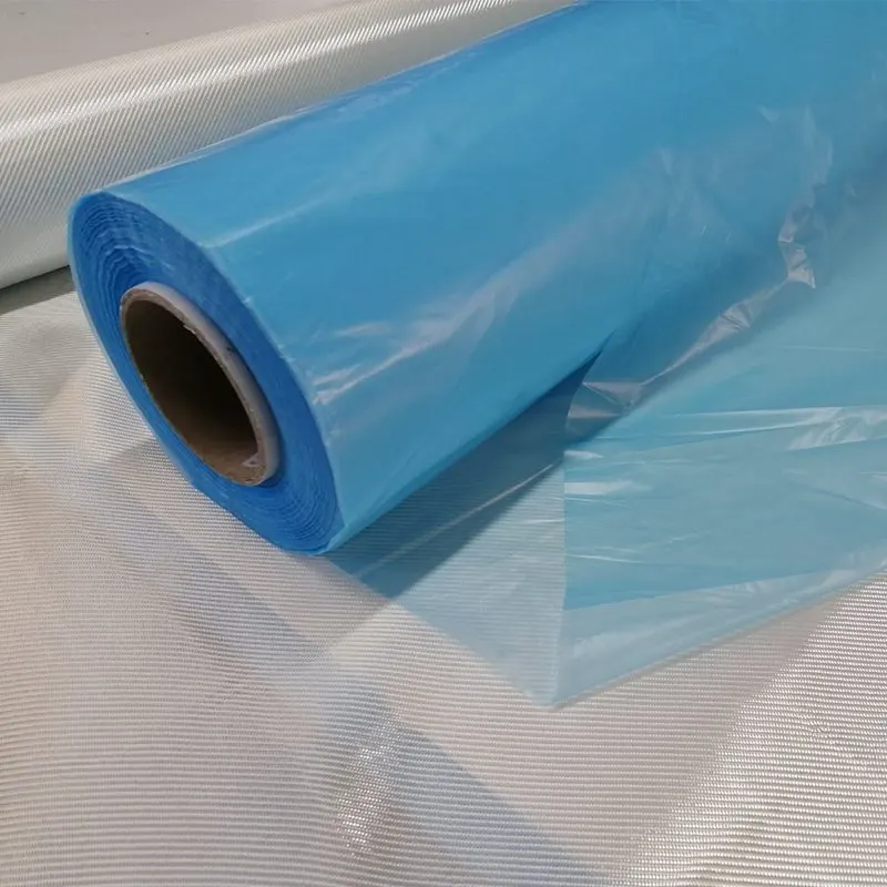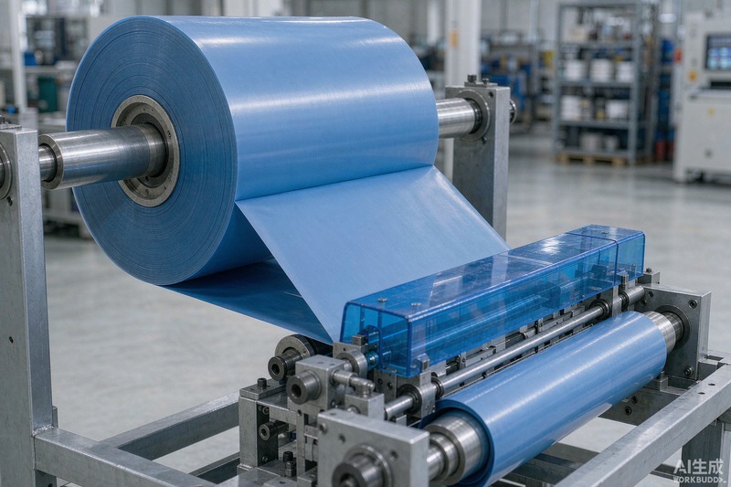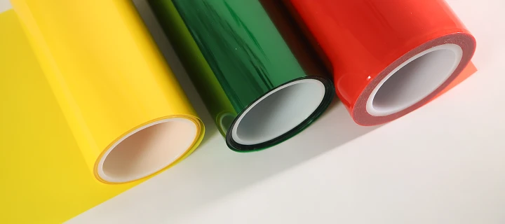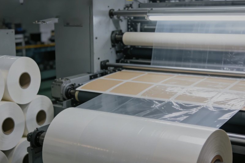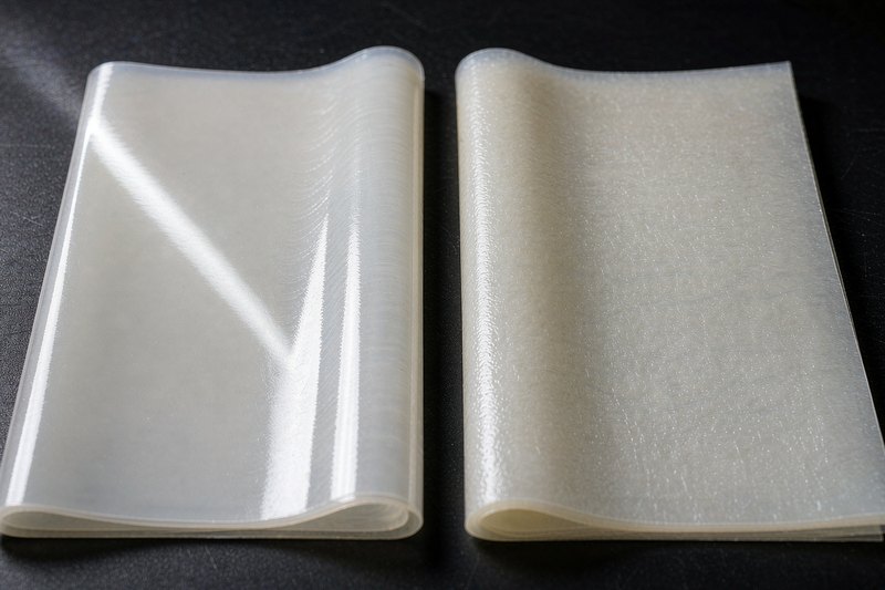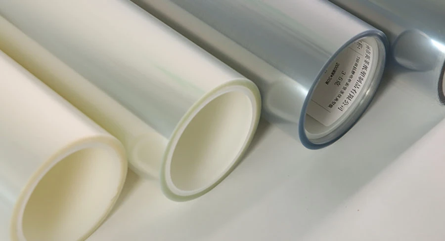
Choosing the right PET release liner for OCA (Optically Clear Adhesive) bonding is a primary determinant of yield in display manufacturing. OCA films are soft, elastic, and prone to deformation, meaning any surface irregularity, inconsistent peeling force, or microscopic contamination on the carrier film transfers directly onto the adhesive layer.
To achieve defect-free lamination in touch panels, cover glass, and OLED/LCD modules, engineers must evaluate three primary parameters: peel force differential stability, surface smoothness and optical cleanliness, and release coating chemistry. This technical guide outlines how to configure release force ratios, prevent optical distortion and micro-bubbles, select compatible coating formulations, and validate liner lots prior to mass production.
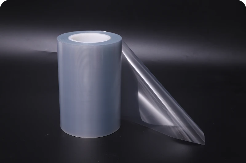
The Critical Role of PET Release Liners in High-Yield OCA Optical Bonding
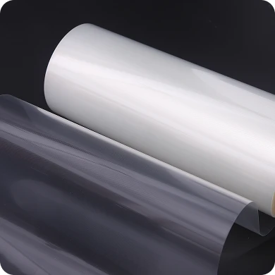
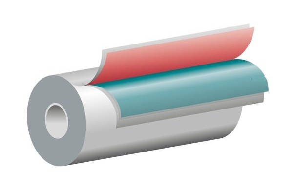
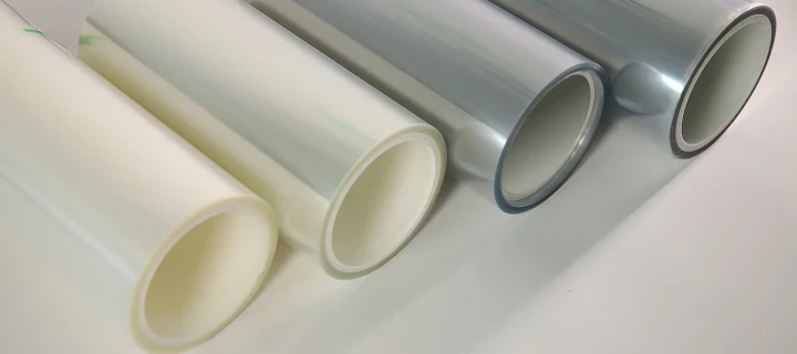
In optical bonding operations, an OCA core is sandwiched between two protective PET liners: an easy-release (light) liner and a tight-release (heavy) liner. Unlike standard packaging or industrial masking films, a PET release liner for OCA functions as a high-precision optical carrier. It must preserve adhesive thickness uniformity and maintain a pristine surface finish until the final autoclave curing cycle is complete.
When a release film displays micro-roughness or uneven cross-web coating, the adhesive copies these micro-textures. Once laminated to a polarizer or cover glass, these impressions trap air, causing micro-bubbles that cannot be eliminated by autoclave pressure. In addition, unstable peel forces during automated high-speed peeling can stretch the soft OCA, resulting in localized optical distortion (Mura) or edge delamination. High-yield display lamination relies on specifying an optical-grade PET substrate engineered to maintain structural flatness, chemical inertness, and cleanroom-verified surface purity.
Key Selection Criteria: Engineering Parameters That Dictate Bonding Success
Selecting a release film for optical clear adhesives requires balancing mechanical peel behaviors against strict optical tolerances.
1. Release Force Profile and Differential Ratio Stability
OCA lamination is a two-step process. First, the easy-release liner is removed so the exposed OCA can be laminated to the display sensor or glass. Second, the tight-release liner is stripped to complete the final assembly.
Differential Release Ratio: To prevent accidental pre-stripping of the wrong liner, manufacturers must maintain an adequate release force ratio between the light and heavy sides. In high-speed automated peel lines, this differential must remain consistent across ambient temperature and humidity shifts.
Peel Dynamics: The release profile must remain flat across the entire length of the web. Sharp spikes in release force (the “stick-slip” phenomenon) shock the adhesive bed, creating thickness variations and line defects.
2. Optical Quality: Haze, Transmittance, and Surface Flatness (Ra)
The physical topography of the PET substrate mirrors directly onto the wet out OCA:
Surface Roughness (Ra): A smooth liner surface yields an optically clear adhesive boundary. Excessive surface roughness scatters light, increasing final stack haze.
Dimensional Stability: Biaxially oriented PET liners must exhibit minimal thermal shrinkage during drying, slitting, and storage to prevent curl or tension-induced film distortion.
3. Cleanroom Standards, Particle Control, and Static Dissipation
Display bonding failure is frequently traced to particulate contamination:
Particle Limits: Release liners for OCA must be coated and converted in controlled cleanroom environments (typically ISO Class 5 to Class 7 equivalent conditions, subject to supplier verification). A single airborne fiber or particle pressed into the OCA creates an unrecoverable focal void.
Static Dissipation (ESD Control): High-speed peeling of PET liners generates significant triboelectric charges. Without anti-static treatments, the charged film attracts airborne debris and risks electrostatic damage to sensitive TFT circuits.
Silicone vs. Fluorosilicone Coatings: Matching Liner Chemistry with OCA Resin Types
The choice of release coating chemistry depends strictly on the chemical base of the optically clear adhesive. Using mismatched chemistry leads to either liner lock-up (inability to peel) or silicone transfer that ruins optical clarity.
| Evaluation Criterion | Standard Silicone Release Coating | Fluorosilicone Release Coating |
|---|---|---|
| Compatible OCA Resin | Acrylic-based OCA formulations | Silicone-based OCA & specialized synthetic rubbers |
| Typical Release Profile | Broadly customizable (very light to heavy release) | Specialized, tightly controlled low-to-medium release |
| Subsequent Adhesion Retention | High (>90% when fully cross-linked) | Very high, near-zero migration |
| Risk of Silicone Migration | Moderate if unreacted silicone oligomers remain | Extremely low; chemically inert matrix |
| Cost Efficiency | Highly cost-effective for high-volume consumer displays | Higher raw material cost; used for harsh-environment/automotive displays |
Acrylic-based OCA: Most mobile displays and commercial touchscreens utilize acrylic adhesives. These adhesives release cleanly from silicone-coated release film formulations, provided the thermal or UV cure rate is high enough to prevent unreacted siloxane migration into the adhesive layer.
Silicone-based OCA: Demanded in automotive and outdoor displays requiring high UV resistance and wide operating temperature ranges. Because silicone adhesives bond aggressively to standard silicone coatings, they require specialized fluorosilicone liners to provide a stable, peelable release boundary.
Troubleshooting Display Lamination Defects: Root Causes in Release Liners
When bonding defects arise on the assembly line, process engineers can identify liner-related root causes through the following troubleshooting matrix:
| Defect Observed | Potential Release Liner Root Cause | Recommended Countermeasure |
|---|---|---|
| Persistent micro-bubbles after autoclave | Substrate surface roughness (Ra) is too high, or localized micro-dewetting exists on the coating. | Switch to an optical-grade PET liner with verified low surface roughness and uniform coating laydown. |
| Jitter lines / Thickness variations | Stick-slip peeling caused by high cohesive friction or uneven release agent curing. | Adjust release force specification; verify that the supplier uses high-curing formulations that deliver smooth peel dynamics. |
| Pre-lamination lift-off (wrong side peels) | Insufficient differential release force between the top (easy) and bottom (tight) liners. | Recalibrate liner pairing to widen the release force ratio between easy and tight sides. |
| Post-lamination haze or optical spots | Low cross-linking in the release coating, causing unreacted silicone oil migration into the OCA. | Verify the subsequent adhesion strength (SAS) metrics with the liner manufacturer. |
| Particle inclusions and pinholes | Static electricity buildup attracting environmental particles during high-speed slitting or peeling. | Implement an anti-static treated PET liner and check ionizer performance at peeling stations. |
B2B Sourcing Protocol: A 4-Step Validation Checklist for Process Engineers
Before approving a new optical-grade release film for series production, engineering and procurement teams should follow a structured qualification protocol:
Substrate & Gauge Uniformity Verification: Confirm nominal PET thickness (common calipers include 50 μm, 75 μm, and 100 μm, depending on machine rigidity requirements) and verify that cross-web thickness variation conforms to tight mechanical tolerances.
Release Force and Thermal Aging Profile: Test initial peel force alongside aged samples (e.g., standard thermal and humidity chamber testing) to ensure release values do not drift upward over shelf life.
Die-Cutting and Slitting Edge Inspection: Ensure the film converts cleanly on rotary or flatbed die-cutters without edge dusting, burrs, or delamination, which can introduce particulate debris into the cleanroom.
Cleanroom Pilot Run & Post-Autoclave Inspection: Execute a pilot lamination run using the designated OCA resin, glass substrate, and autoclave parameters. Inspect post-lamination samples under optical inspection lamps for haze, residual silicone shadows, and bubble retention.
Optimize Your Optical Lamination Yield with Yinfei
Achieving consistent optical clarity and high throughput in display bonding requires tightly specified carrier substrates. Yinfei delivers precision-engineered PET release films configured for the optical clear adhesive market, backed by cleanroom manufacturing, tight release force tolerances, and customized slitting capabilities.
Whether you are qualifying materials for consumer smartphone displays, automotive cockpit panels, or industrial touchscreens, securing the correct liner specification minimizes scrap and protects optical performance.
Key Takeaways
Liner Surface Defines OCA Surface: Soft OCA formulations replicate the topography of the PET carrier; optical smoothness and low surface roughness (Ra) are essential to prevent micro-bubble entrapment.
Differential Ratios Prevent Jamming: Automated pick-and-place and roll-to-roll bonding lines rely on a stable peel force gap between the easy-release and tight-release liners across varying line speeds.
Match Chemistry to the Resin: Use high-cure silicone-coated liners for acrylic OCAs and fluorosilicone liners for silicone-based OCAs to eliminate lock-up and silicone migration defects.
Static and Particle Controls Are Decisive: Cleanroom-manufactured PET liners with anti-static characteristics prevent particulate ingress that compromises display yields.
FAQ
What thickness PET release liner is standard for OCA bonding?
Thickness depends on the processing equipment and display dimensions. Common thicknesses range from 50 μm to 100 μm. Thicker liners (e.g., 75 μm or 100 μm) provide greater structural rigidity to prevent curl and creasing during wide-web lamination, while thinner liners are typically used for smaller die-cut components or secondary covers. Exact thickness must be confirmed against machine handling limits.
How do you prevent silicone migration from the release liner into the OCA?
Silicone migration is prevented by using high-efficiency platinum-cured silicone systems or UV-cured formulations with near-complete cross-linking density. Procuring films with a high Subsequent Adhesion Strength (SAS)—typically specified above 90–95% upon testing—verifies that minimal unreacted siloxane oil transfers to the adhesive.
Why does the differential release ratio matter in OCA manufacturing?
An OCA sheet requires two liners. If the release values between the light-release side and heavy-release side are too close, peeling equipment may inadvertently strip the heavy liner first, stretching the adhesive or stalling automated assembly lines. A clear differential ensures predictable, sequential peeling.
Can industrial-grade PET release films be used for display OCA bonding?
No. Standard industrial liners permit higher surface roughness, wider thickness variations, and relaxed particle allowances. These minor physical imperfections transfer to optically clear adhesives, generating optical distortion, increased haze, and bubble defects under display backlights.