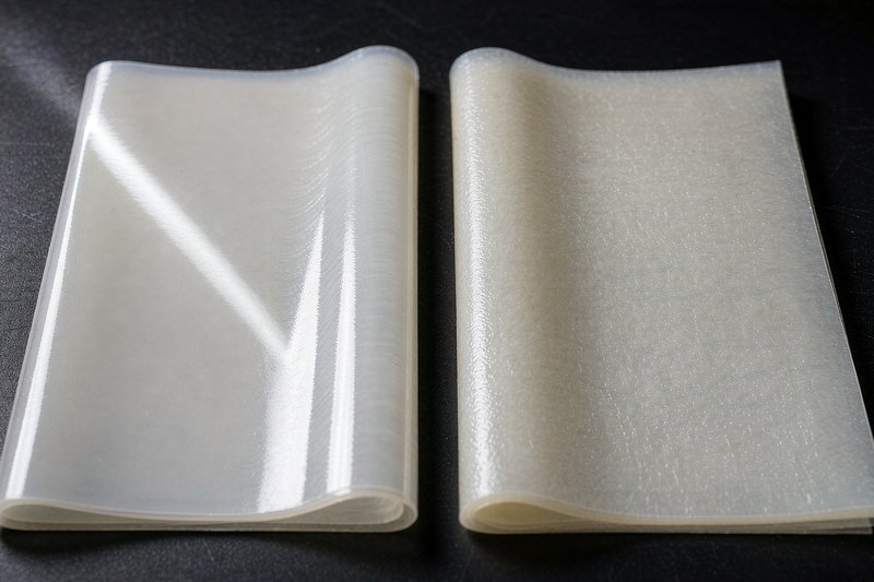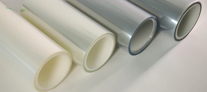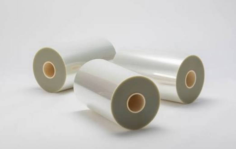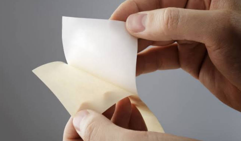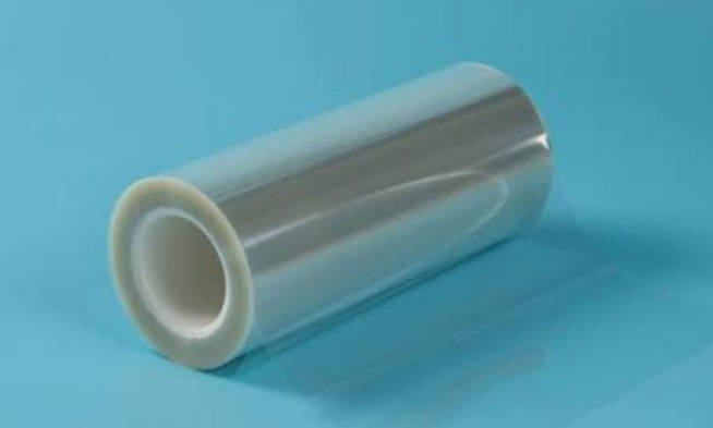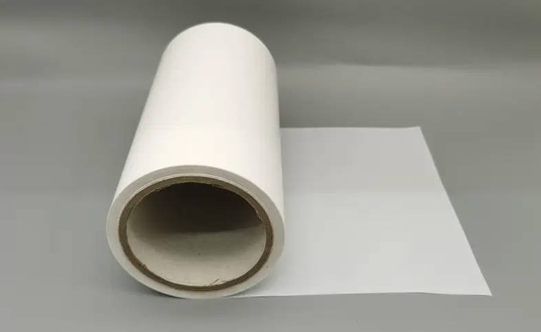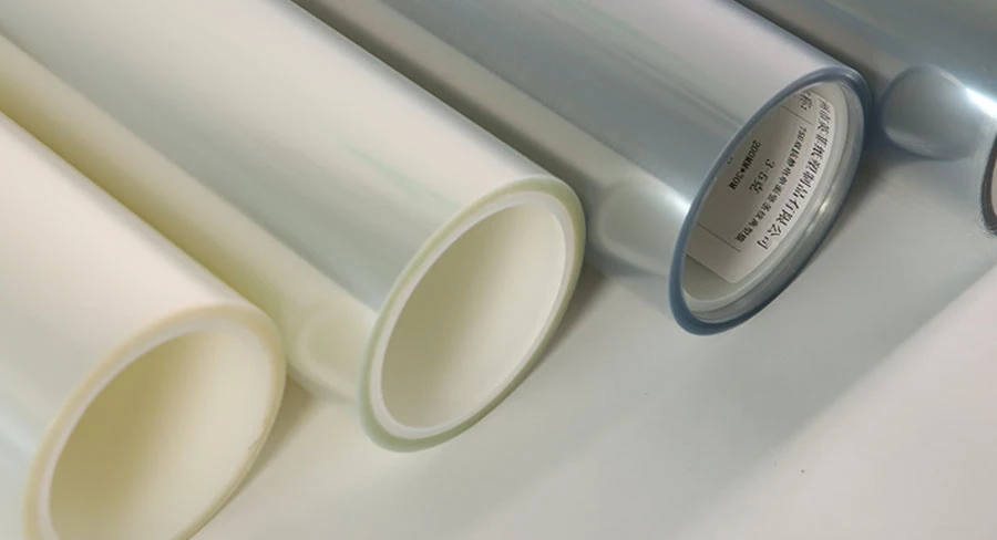
Silicone pressure-sensitive adhesives (PSAs) cannot release cleanly from standard polydimethylsiloxane (PDMS) silicone liners. When laminated against a conventional silicone liner, a silicone adhesive forms chemical bonds and molecular interlocks that lead to irreversible interfacial adhesion, commonly referred to as liner lock-up. Protecting, converting, and applying a silicone PSA requires a specialized fluorosilicone release film engineered with a low-surface-energy fluorocarbon coating to provide a consistent release differential while maintaining adhesive integrity.
Specifying the correct liner requires evaluating chemical compatibility, surface tension differentials, converting line speeds, carrier caliper, and heat exposure during coating and die-cutting. This guide explains why conventional silicone liners fail with silicone adhesives, examines the interfacial surface mechanics of fluorosilicone coatings, compares key material attributes, and outlines an engineering selection framework for cleanroom converting, electronics assembly, and high-temperature masking tapes.
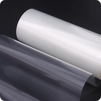
The Silicone Dilemma: Why Standard Silicone Liners Lock Up with Silicone PSAs
In pressure-sensitive adhesive coating and precision die-cutting, liner lock-up occurs when the release backing bonds permanently to the adhesive layer. When paired with acrylic, natural rubber, or polyurethane adhesive chemistries, standard silicone-coated polyethylene terephthalate (PET) films perform reliably because the cured silicone layer provides a chemically mismatched, low-surface-energy surface.
When silicone PSAs contact standard silicone release coatings, that release differential disappears:
| System Architecture | Layer Interface Dynamic | Chemical & Molecular Mechanism | Operational Outcome |
|---|---|---|---|
| Standard Silicone System (Failure with Silicone PSA) | Silicone PSA Layer ↕ (Interface) Polydimethylsiloxane (PDMS) Coating | • Mutual thermodynamic solubility • Rapid molecular interdiffusion • Cross-coupling of residual functional silanes | Severe Interfacial Lock-up (Irreversible fusion, substrate tearing, adhesive transfer) |
| Fluorosilicone System (Engineered for Silicone PSA) | Silicone PSA Layer ↕ (Interface) Fluorosilicone Coated PET Substrate | • Dense fluorocarbon barrier layer • Chemical repulsion & non-wetting interface • High-density crosslinked matrix | Controlled Differential Release (Predictable peel profile, preserved tack, zero adhesive deadening) |
Three distinct interfacial reactions cause standard silicone liners to lock up when exposed to silicone PSAs:
- Thermodynamic Affinity and Spontaneous Wetting: Because both formulations share a siloxane (Si-O-Si) polymer backbone, their critical surface tensions and solubility parameters align closely. The silicone adhesive spontaneously wets out across the silicone liner, preventing the formation of a distinct release boundary.
- Polymer Chain Interdiffusion: Uncrosslinked polymer chains and pendant functional groups within the uncured or pressure-sensitive adhesive matrix migrate across the boundary into the cured silicone coating. Within 24 to 72 hours under ambient pressure, this interdiffusion creates mechanical interlocking at the molecular scale.
- Cross-Phase Silane Coupling: Commercial silicone PSAs and addition-cure thermal release coatings frequently utilize platinum-catalyzed hydrosilylation chemistries. Trace unreacted vinyl (-CH=CH2) and hydride (Si-H) functional groups cross-couple across the interface over time, curing the adhesive mass and the release coating into a single crosslinked elastomer.
Attempting to separate a silicone adhesive from a standard silicone liner under these conditions tears the carrier film, splits the cohesive adhesive mass, or pulls the release coating off the PET backing.
Interfacial Chemistry: How Fluorosilicone Overcomes Silicone-to-Silicone Affinity
Eliminating interfacial lock-up requires replacing standard polydimethylsiloxane (PDMS) coatings with modified fluorosilicone polymers. Fluorosilicone release chemistries introduce fluorinated side chains (such as trifluoropropyl or perfluoroalkyl groups) along the polysiloxane polymer backbone, altering surface thermodynamics and wetting behavior.
Surface Energy and Molecular Repulsion: Fluorocarbon vs. PDMS
Standard PDMS release coatings provide surface energy levels around 20–22 mN/m. While this low energy easily repels organic adhesives such as acrylics (35–40 mN/m) or hot-melt rubbers, it matches the surface tension of silicone adhesives (20–24 mN/m), resulting in zero effective wetting barrier.
In contrast, fluorosilicone release systems reduce surface energy to approximately 14–18 mN/m. The high electronegativity, tight atomic radius, and low polarizability of fluorine atoms generate a dense electron shield. This fluorocarbon structure repels organosilicone polymer chains, preventing the adhesive from wetting or penetrating the release matrix.
| Material / Chemistry Type | Typical Surface Energy (mN/m) | Wetting Behavior with Silicone PSA | Interfacial Release Capability |
|---|---|---|---|
| Acrylic Adhesives | 35–40 | High wetting on standard silicone | Releases easily from standard PDMS silicone |
| Silicone Pressure-Sensitive PSAs | 20–24 | Spontaneous wetting on PDMS | Severe wetting and molecular lock-up |
| Standard PDMS Silicone Coatings | 20–22 | Equivalent surface tension to PSA | Incompatible with silicone PSAs; zero release |
| Fluorosilicone Release Coatings | 14–18 | Repels organosilicone chains | Stable differential release barrier |
Preventing Silicone Migration and Protecting Subsequent Adhesion (ROA)
In precision electronics, thermal management, and medical die-cutting, converting yields depend on retaining the adhesive’s original bonding strength. Poorly anchored or incompletely cured release liners permit low-molecular-weight siloxane oligomers (free silicone oils) to leach into the PSA layer.
When unreacted silicone oils migrate into an adhesive:
- Migrated siloxanes concentrate at the adhesive surface, forming a weak boundary layer that impairs wet-out on target bonding substrates.
- The Subsequent Adhesion Strength—measured via Subsequent Adhesion Loss (ROA) testing—drops outside engineering tolerances.
- The functional adhesive layer risks delamination, edge lifting, or premature cohesive failure during downstream thermal cycles.
- Formulating with addition-cured, tightly crosslinked fluorosilicone networks prevents extractable silicone fractions from contaminating sensitive adhesive surfaces. Converters and tape coaters processing high-performance assemblies should specify verified precision release film solutions to eliminate silicone migration risks.
Direct Comparison: Fluorosilicone vs. Standard Silicone Release Liners with Silicone PSAs
The table below contrasts fluorosilicone-coated PET against standard silicone-coated PET when laminated to silicone pressure-sensitive adhesives:
| Technical Parameter / Property | Standard Silicone (PDMS) Liner + Silicone PSA | Fluorosilicone Coated PET Liner + Silicone PSA |
|---|---|---|
| Primary Chemical Backbone | Polydimethylsiloxane (PDMS) | Perfluoroalkyl-functionalized polysiloxane |
| Interfacial Compatibility | Chemically incompatible; causes irreversible lock-up | Fully compatible; delivers stable differential release |
| Typical Surface Energy | ≈ 20–22 mN/m | ≈ 14–18 mN/m |
| Release Stability After Aging | Fails; peel force escalates rapidly within 24–72 hours | High; peel resistance remains flat across thermal/humidity aging |
| Adhesive Transfer / Ghosting | Severe cohesive splitting or tearing of carrier film | Clean interfacial separation without adhesive residue |
| Subsequent Adhesion (ROA) | Substantially degraded by migratory silicone fractions | Preserved; maintains baseline tack and peel strength |
| Thermal Processing Ceiling | Stable up to 150–200°C, but lock-up accelerates with heat | Retains release differential across continuous thermal curing cycles |
| Relative Material Cost Profile | Standard baseline industrial cost | Premium cost profile driven by specialized fluoromonomer synthesis |
While standard silicone films deliver an economical solution for broad-market acrylic tapes and paper labels, applying them to silicone PSAs causes converting line shutdowns and part failures. Fluorosilicone liners remain the primary engineering choice for handling silicone adhesive chemistry.
Selection Framework: Specifying the Right Fluorosilicone Release Film for Converting and Die-Cutting
Selecting an optimal liner construction requires balancing target peel values, PET carrier thickness, web tension parameters, and mechanical stability across high-speed rotary die stations.
| Selection Stage | Engineering Focus | Critical Specification Variables | Primary Failure Risk if Mismatched |
|---|---|---|---|
| Stage 1 | Adhesive Characterization | • Catalyst chemistry (Pt-cure vs. Peroxide) • Tack level and viscoelastic profile • Applied dry adhesive thickness (μm) | Chemical cross-coupling; adhesive shock delamination |
| Stage 2 | Peel Force Profiling | • Easy / Light release range (3–10 g/in) • Medium release range (15–35 g/in) • Firm / Differential range (40–80+ g/in) | Premature pre-dispensing (flying) or part deformation during matrix stripping |
| Stage 3 | Carrier Caliper Sizing | • Thin gauges: 23–36 μm • Converting baseline: 50–75 μm • Rigid sheet / Platen: 100–125 μm+ | Web breakages during die striking; deep liner scoring; platen curl |
| Stage 4 | Thermal & Kinetic Validation | • Web tension control settings • Oven drying dwell times and peak temperatures • Dynamic release peel angles (90° vs. 180°) | Thermal relaxation/curling; velocity-dependent peel chatter (zipper effect) |
Matching Release Force: Light, Medium, vs. Tight Peeling Curves
Peel performance is typically verified via standardized 180° or 90° mechanical pull testing at controlled pull rates (typically 300 mm/min, per FINAT or ASTM standards):
- Light / Easy Release (3–10 g/in): Essential for wide-web converting, thin silicone transfer tapes, and delicate silicone elastomeric gaskets where high separation force could distort or stretch unsupported adhesive layers.
- Medium Release (15–35 g/in): The industry baseline for continuous slitting, high-speed rotary die-cutting, and automated label dispensing. This profile provides adequate retention to prevent premature web pre-dispensing during fast line-tension fluctuations.
- Tight / Firm Release (40–80+ g/in): Designed for differential double-sided constructions (such as silicone-to-acrylic differential tapes or heavy silicone transfer films). The secondary liner must release with higher resistance than the primary liner to ensure clean, single-sided separation during final installation.
Base Carrier Evaluation: PET Substrate Thickness and Thermal Shrinkage
Biaxially oriented PET provides the tensile strength and dimensional stability needed for precision converting:
- 23 μm to 36 μm Caliper: Maximizes linear footage per roll and reduces overall packaging weight. Well suited for thin thermal interface laminates where tight roll diameters are required.
- 50 μm to 75 μm Caliper: The industry benchmark for rotary die-cutting and high-speed kiss-cutting. It provides sufficient anvil support, resists cut-through during sharp rotary tool strikes, and maintains flat feeding.
- 100 μm to 125 μm+ Caliper: Engineered for flatbed platen processing, thick elastomeric gap pads, and sheeted electronic components requiring flat, curl-free presentation.
PET thermal shrinkage must be verified before running films through continuous high-temperature drying ovens. Inadequate heat stabilization leads to web curling, tension variations, and uneven adhesive coat weights.
Converting Speeds and High-Speed Unwinding Dynamics
Static peel forces measured at low laboratory testing speeds (0.3 m/min) do not correlate linearly with automated converting speeds (30–150 m/min).
As peel velocity accelerates, poorly formulated fluorosilicone coatings may exhibit sharp increases in peel resistance. This velocity-dependent peel spike causes web chatter, high-frequency noise, and edge tear failures. High-quality fluorosilicone release films maintain flat release force curves across varying unwinding and stripping speeds.
Critical Applications Demanding Fluorosilicone Liners
Industrial sectors with strict thermal, chemical, and mechanical requirements depend on silicone PSA and fluorosilicone release systems to handle demanding operational environments.
| Industrial Application | Material Construction | Operational Challenges | Primary Role of Fluorosilicone Film |
|---|---|---|---|
| EV Battery Thermal Management | Ceramic-filled silicone gap fillers and TIM pads | High matrix tack, soft cohesive strength, wide-web formats | Delivers uniform, low-force release without tearing soft, filled elastomeric pads |
| High-Temp Electronics Masking | Polyimide (Kapton) or glass cloth backing + silicone PSA | Exposure to wave soldering and reflow temperatures (>200°C) | Maintains dimensional stability and prevents liner lock-up during heat cycles |
| Medical Wearables & Wound Care | Biocompatible silicone gel adhesives (SGAs) | Skin-contact purity requirements, cleanroom converting standards | Prevents siloxane oil migration, preserving adhesive tack and biocompatibility |
| Flexible Circuit Board (FPC) Bonding | Double-sided polyimide tapes with differential silicone coats | Tight die-cutting tolerances, multi-layer kiss-cutting | Ensures differential release values so liners strip in correct sequence |
Thermal Interface Materials (TIM) and Gap Fillers in EV Batteries and Electronics
Electric vehicle battery packs, high-frequency radar modules, and power semiconductor assemblies require silicone-based gap pads and phase-change thermal interface materials. These pads provide thermal transfer, electrical isolation, and vibrational damping.
Because uncured or soft-cured silicone gap fillers have high surface tack, converting operations rely on fluorosilicone release film liners to deliver uniform release across wide-format rolls without tearing the fragile, filled elastomeric matrix.
High-Temperature Silicone Adhesive Tapes
Polyimide, woven fiberglass, and PTFE-backed adhesive tapes engineered for wave soldering, powder-coat masking, and aerospace composite debulking use aggressive silicone PSAs. These tapes must withstand processing temperatures above 200°C. Fluorosilicone PET liners protect the functional adhesive layer across long storage cycles, ensuring the tape unwinds smoothly and adheres completely during downstream assembly.
Medical and Wearable Silicone Skin Adhesives
Advanced wound care dressings, transdermal drug delivery patches, and wearable patient monitoring sensors favor soft silicone gel adhesives (SGAs) because they adhere securely to skin without tearing fragile epidermal layers during removal. Fluorosilicone-coated films serve as process carriers and packaging covers for these materials, preserving sterility and adhesive purity without leaching non-biocompatible process oils.
Troubleshooting Common Processing Failures: Prevention & Root Causes
Processing silicone adhesives with release liners can expose production defects if raw material parameters drift. The following troubleshooting reference outlines common conversion issues, root causes, and corrective actions:
| Defect Phenomenon | Root Cause Identification | Corrective Engineering Action |
|---|---|---|
| Complete Release Lock-Up | Standard silicone liner used inadvertently, or cross-contamination occurred on a dual-side coating line. | Confirm the presence of a fluorocarbon-modified coating via FTIR analysis; switch to fluorosilicone stock. |
| “Zipper Effect” (Stick-Slip Peeling Noise) | Uneven crosslinking density or erratic coating thickness, causing the adhesive front to stall and release abruptly. | Verify coating caliper uniformity; audit web tension; transition to a precision reverse gravure-coated liner. |
| Subsequent Adhesion Loss (Adhesive Ghosting/Deadening) | Free, unreacted silicone molecules from the liner coating have migrated into the silicone PSA matrix. | Specify a fully cured, low-extractable fluorosilicone chemistry; verify supplier ROA test reports. |
| Die-Cutting Cut-Through or Deep Liner Scoring | PET caliper variations across the web width, or inadequate tensile modulus for rotary anvil strikes. | Increase PET liner thickness (e.g., upgrade from 36 μm to 50 μm or 75 μm); calibrate tooling tolerances. |
| Edge Delamination (Liner Pop-Off During Slitting) | Release force is too light for the web tension and stiffness of the selected adhesive tape backing. | Step down to a firmer release specification; evaluate and adjust slitting shear angles and rewind tension. |
Key Takeaways
- Chemical Necessity: Standard silicone liners bond permanently with silicone PSAs due to identical chemical backbones and molecular interdiffusion. Fluorosilicone release coatings provide the lower surface energy (14–18 mN/m) needed to prevent wetting and ensure clean release.
- Preserving Adhesive Integrity: Inferior or poorly cured liners release free silicone oils that migrate into the adhesive bed, degrading Subsequent Adhesion (ROA). High-crosslink fluorosilicone coatings prevent silicone transfer and preserve adhesive tack.
- Matching Thickness to Process: Match PET carrier thickness to downstream mechanical demands: 23–36 μm for compact shipping rolls, 50–75 μm for high-speed rotary die-cutting, and 100–125 μm+ for flatbed platen processing and thick gap pads.
- Testing Dynamic Release Speeds: Always measure release values across production converting velocities (30–100+ m/min) rather than relying solely on low-speed laboratory peel data.
Frequently Asked Questions (FAQ)
Can I use a standard silicone release film if I peel it off immediately after lamination?
No. Even brief contact between a silicone pressure-sensitive adhesive and a standard silicone coating initiates wetting and molecular migration. While the liner might separate under high manual force immediately after lamination, adhesive performance degrades, and subsequent adhesion loss will occur. Within 24 to 48 hours, chemical cross-linking generally produces total interfacial lock-up.
What standard test methods evaluate fluorosilicone release liners?
Standard industrial test protocols include:
- FINAT FTM 3 & FTM 4: For low-speed and high-speed release evaluation (180° peel angle).
- FINAT FTM 10 & FTM 11: For subsequent adhesive strength and silicone oil migration testing.
- ASTM D3330: For standard peel adhesion testing of pressure-sensitive tapes.
- ASTM D6862: For measuring resistance to peeling in 90° configurations.
Why is fluorosilicone release film more expensive than standard silicone film?
Fluorosilicone coatings utilize fluorinated silicone monomers, which require complex chemical synthesis. In addition, applying fluorosilicone requires specialized platinum catalysts, tightly monitored cleanroom coaters, and strict curing controls to prevent surface defects. While unit costs are higher, fluorosilicone liners are necessary to process and convert silicone-based PSAs successfully.
What technical information should buyers provide when requesting custom release film?
To specify an appropriate liner construction, supply your converter with:
- Adhesive type and specific chemistry (platinum-cured vs. peroxide-cured silicone).
- Target dry adhesive coat weight (thickness in micrometers or grams per square meter).
- Desired release force range (ultra-light, medium, or tight differential).
- Processing temperatures and dwell times during web drying or component assembly.
- Slitting width, core size, winding orientation, and die-cutting machinery specifications.