Kiss-cutting depth control is governed by a closed mechanical tolerance loop between cutting blade height, anvil roll concentricity, and the backing liner’s gauge uniformity. When a die-cut line exhibits inconsistent depth—either penetrating the liner or failing to sever adhesive cleanly—the cause is rarely an isolated pressure error on the press. Instead, depth variation results from cumulative dimensional stack-up across machine hardware and substrate thickness. Controlling this micron-scale interface requires balancing dynamic rotary clearances against the physical compressibility of the carrier film.
This guide examines how tooling geometry, anvil deflection, and liner caliper variations interact, outlines a diagnostic troubleshooting process for converters, and establishes the substrate specifications needed to eliminate cut-through defects.
The Micron-Level Challenge: Anatomy of Kiss-Cutting Depth Control
In rotary and flatbed converting, kiss-cutting requires severing the facestock and pressure-sensitive adhesive layer completely while leaving the underlying release liner uncut and mechanically intact. The functional process window for this operation is extremely narrow, typically measured in single-digit microns.
| Structural Layer / Tooling Component | State / Dynamic Condition | Mechanical Action & Load Distribution |
|---|---|---|
| Die Blade Tip | Controlled Height & Radii | Applies downward cutting load to shear composite layers. |
| Facestock | Completely Severed | Penetrated fully by the leading edge of the cutting blade. |
| Adhesive Layer | Completely Severed | Cleaved without adhesive stringing or hydraulic push-back. |
| Release Coating | Preserved & Uncompromised | Retains surface boundary integrity and anti-stick properties. |
| Liner Substrate | 100% Intact (Zero Penetration) | Serves as mechanical stop; absorbs reactive cutting force. |
| Anvil Roll Body / Base | Hardened Base (Zero Deflection) | Delivers uniform opposing reactive force across the nip point. |
Depth variation occurs when the cumulative tolerance stack-up exceeds the thickness tolerance of the liner itself. In production, four mechanical variables sum together at the point of cut:
- Radial runout and height consistency of the cutting die cavity.
- Anvil cylinder deflection and journal runout under mechanical pre-load.
- Fluid dynamics and hydraulic resistance of the adhesive layer.
- Total thickness consistency (caliper) and tensile modulus of the liner substrate.
When converters encounter periodic liner scoring (liner strike) or intermittent web breakage during high-speed matrix stripping, adjusting global impression pressure often compounds the failure. Increasing pressure forces the blade through thin sections of the substrate, whereas decreasing pressure leaves adhesive strands unsevered in thicker web lanes. Maintaining an open converting window requires stabilizing both mechanical tooling and raw substrate specifications.
The Hardware Duo: Rotary Blade Height and Anvil Roll Dynamics
Precision kiss-cutting requires rigid mechanical alignment before the web enters the nip point. The tooling assembly must deliver uniform downward clearance across the full working width of the cylinder.
Blade Bevel Angle, Tip Radii, and Penetration Behavior
Die blade geometry dictates the stress concentration applied to the release backing:
- Single vs. Double Bevel: Double-bevel symmetrical blades distribute lateral displacement equally into the face material, reducing lateral blade walk. Single-bevel configurations push material outward, creating asymmetrical shear stresses that increase the risk of edge-fracturing brittle liners.
- Included Angle: Narrow blade angles (e.g., 60° to 70°) penetrate high-tack adhesives with minimal resistance, whereas wider profiles (75° to 90°) provide structural rigidity, reducing tip deformation on tough polymeric facestocks.
- Tip Radius: A sharp blade tip cleanly cleaves the adhesive matrix. As the tip radius erodes from abrasive pigments or inorganic fillers, cutting gives way to hydraulic compression. The blunt tip displaces adhesive laterally, transferring blunt impact energy directly into the liner base.
Anvil Runout, Deflection, and Bearer Ring Alignment
The anvil cylinder serves as the precision baseline against which blade depth is referenced. Any geometric error in this component directly translates into depth fluctuations:
- Radial Runout (Total Indicated Runout – TIR): High-precision converting demands an anvil TIR within extremely tight machine limits. If an anvil exhibits journal or body runout, depth fluctuates cyclically with every revolution of the roll, producing repeating cut-through patterns on the web.
- Cylinder Deflection: Under high pneumatic or hydraulic loading, standard anvil bodies bow slightly at the center. This deflection increases blade-to-anvil clearance along the mid-web while over-compressing the outer lanes near the bearer rings.
- Bearer Ring Pre-Load: Bearer rings maintain the calculated air gap between the cutting cylinder and the anvil body. Contamination, foreign particulate denting, or lack of lubrication on the bearer surfaces causes harmonic vibration, leading to micro-chatter marks along the cut path.
The Overlooked Factor: Why Liner Gauge Consistency Dictates Cut Consistency
Machine hardware fixes the absolute mechanical boundary, but the carrier liner provides the reactive surface that stops blade travel. If liner thickness fluctuates, the effective kiss-cut depth varies continuously throughout the roll.
Gauge (Caliper) Variation: Cross-Web (CD) and Machine-Direction (MD) Tolerances
Converting lines run at high linear speeds, making dynamic depth readjustment impractical for localized caliper variations. Thickness deviations manifest in two forms:
- Machine Direction (MD) Variation: Gradual or cyclical caliper shifts along the length of the web. These cause intermittent cutting failures over successive run meters, alternating between clean cuts and liner strikes.
- Cross-Direction (CD) Variation: Gauge bands or wedge profiles across the roll width. If the operator sets the cutting depth to suit the thickest lane of the web, the die will fail to cut through adhesive in the thinnest lane.
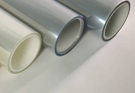
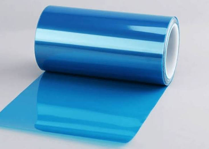
- A consistent release film substrate mitigates this risk by maintaining uniform caliper tolerances across both axes, preventing localized punch-through under fixed tooling clearances.
Substrate Compressibility: Polyester (PET) vs. Paper-Based Liners Under Blade Load
The material composition of the backing directly governs how it reacts when the blade tip meets the release interface. Paper-based backings (such as glassine or supercalendered kraft) feature an open, fibrous structure with high natural compressibility. Under blade impact, cellulose fibers compress non-linearly, which can cause internal fiber crushing (core burst) even when the surface appears uncut.
In contrast, biaxially oriented polyester (PET) release films offer a significantly higher elastic modulus and structural density. Under sharp die impact, PET resists micro-compression, functioning as a rigid mechanical barrier.
| Performance Attribute | Glassine / Paper Liners | Biaxially Oriented PET Release Film | Impact on Kiss-Cutting Depth Control |
|---|---|---|---|
| Caliper Uniformity | Moderate (fiber flocculation causes micro-variations) | High (extrusion and biaxial orientation ensure flatness) | Eliminates localized depth variations across wide web widths. |
| Material Compressibility | High (porous fiber structure yields under peak point load) | Minimal (dense polymer chains resist plastic deformation) | Prevents the blade tip from sinking into the liner during die impact. |
| Tear / Burst Resistance | Prone to fiber fracture when scored or nicked | Superior puncture resistance along die perimeter | Allows matrix stripping at high web speeds without web breakage. |
| Moisture Sensitivity | Expands/contracts with ambient relative humidity | Dimensionally stable across moisture and temperature shifts | Prevents web curling and off-gauge expansion in humid facilities. |
Using a precision-gauge PET release film allows converters to establish tighter blade clearances without risk of baseline rupture.
The Tri-Part Interaction: Modeling the Gap Dynamic During Production
Kiss-cutting is a dynamic process where machine dimensions, thermal properties, and raw materials continuously shift during production.
| Variable Parameter | Equation Representation | Mechanical Impact on Dynamic Clearance (Geff) |
|---|---|---|
| Die Height Baseline | Hdie | Determines the upper physical limit of the cutting stroke. |
| Anvil Runout / Baseline | Ranvil | Governs baseline concentricity and rotational runout variance. |
| Thermal Expansion | Δ T | Tooling friction expands cylinders radially, narrowing the gap. |
| Liner Substrate Caliper | Cliner | Primary baseline substrate thickness; stops blade descent. |
| Facestock Thickness | Cface | Initial structural layer to be cut through during penetration. |
| Adhesive Displacement | Cadh | Fluid back-pressure resisting high-speed blade travel. |
The Micro-Gap Equation: Dynamic Clearance Stack-Up
In static setups, clearance is verified via lead foil or carbon imprint tests. In dynamic production, however, the gap shifts:
- Thermal Expansion: Rotary dies and anvil blocks generate frictional heat at bearer rings and journal bearings. As temperatures rise from startup to equilibrium, steel cylinders expand radially. A few degrees of temperature increase can expand cylinder radii by multiple microns, transforming an acceptable clearance into an aggressive liner strike.
- Hydrodynamic Adhesive Back-Pressure: Highly viscous adhesives generate hydraulic resistance at elevated converting speeds. The adhesive must be displaced ahead of the blade edge. If the blade bevel is too blunt or press speed increases without a corresponding adjustment in cutting force, this hydraulic barrier deflects the blade upward, causing uncut adhesive strands.
The Kiss-Cut Safety Window
The allowable safety window is the margin between the minimum depth required to release the facestock cleanly and the maximum penetration the liner can sustain without structural failure:
Margin = Cliner – (Tolerancetooling + Toleranceliner)
If the combined tolerance of the tooling (Tolerancetooling) and the substrate (Toleranceliner) approaches or exceeds the nominal liner thickness (Cliner), process control is lost. Because tooling precision is mechanically constrained by the press build, reducing substrate caliper variation is the primary method to expand the operational safety margin.
Step-by-Step Troubleshooting: Distinguishing Tooling Wear from Liner Gauge Defects
When cut-through or incomplete cut issues arise, use the following systematic troubleshooting procedure to isolate tooling errors from raw material defects.
| Inspection Step | Diagnostic Criteria | Failure Classification | Primary Corrective Action |
|---|---|---|---|
| 1. Periodicity Check | Marks repeat at intervals matching roll circumference. | Mechanical Tooling Error | Inspect anvil roll and die with dial indicator; clean bearer rings. |
| 2. Random Spot Check | Non-cyclical strikes across machine direction. | Substrate Gauge Variation | Measure baseline liner thickness across 10 defect zones with micro-caliper. |
| 3. Web Profile Check | Center cut differs from web edges (center uncut or edges cut). | Anvil Roll Deflection | Back off excessive bridge load or install high-rigidity crowned anvil. |
| 4. Structural Integrity Check | Backing tears or bursts without visible blade penetration. | Material Modulus Failure | Switch fragile paper liners to high-tensile, incompressible PET release film. |
| Symptom | Tooling Root Cause | Liner Substrate Root Cause | Corrective Action |
|---|---|---|---|
| Periodic Cut-Through (repeats at fixed linear intervals matching roll circumference) | Anvil body runout, localized chip on bearer ring, or bent cylinder journal. | Unlikely to cause repeating periodic defects unless patterned roll deformation occurred during slitting. | Inspect anvil cylinder and die with a dial indicator (check TIR); clean and stone bearer rings. |
| Intermittent / Random Liner Strike (no fixed linear periodicity) | Mechanical vibration, worn bearer block bearings, or loose pressure bridge bolts. | High cross-web or longitudinal caliper variation; uncalibrated gauge bands across the master roll. | Measure baseline liner thickness across 10 consecutive defect zones with a micro-caliper; verify dimensionally stable release liners are within specification. |
| Edge-Lane Cut-Through (cuts cleanly in the center, cuts through at web edges) | Under-loaded pressure bridge causing deflection, or tapered anvil roll geometry. | Edge-bead thick spots or slitting-induced edge stretch from rewinding tension. | Check anvil leveling and bridge pressure; evaluate edge-to-edge substrate thickness profile. |
| Mid-Web Incomplete Cut (cuts cleanly on edges, fails to sever adhesive in center) | Excessive downward bridge force causing anvil roll deflection (center dips away from the die). | Thinner gauge profile along the centerline of the web slit. | Back off excessive bridge pre-load; switch to a larger-diameter, high-rigidity anvil or crowned anvil roll. |
| Liner Delamination / Core Burst (no visible blade puncture, but backing ruptures during dispensing) | Dull blade tip applying excessive blunt compression rather than clean shearing. | Low internal bond strength, porous paper base, or fiber fracturing under compressive load. | Sharpen or replace cutting cylinder; replace fragile paper liners with high-tensile PET release film. |
Specifying Release Films for Critical Kiss-Cutting: What Converters Must Require
To maintain high yields in precision converting lines—such as electronic gaskets, optical clear adhesives (OCA), and medical diagnostic strips—procurement and engineering teams must verify material specifications before ordering release films.
Caliper Runout Targets: What Micron Tolerance to Demand
Converters should establish explicit thickness tolerance thresholds with their film suppliers:
- Nominal Gauge Consistency: Demand high-precision PET film bases where caliper consistency is strictly controlled across both the web center and lane edges.
- Surface Topography and Flatness: Verify that the film surface is free from micro-voids, gel spots, and thickness streaks. Surface defects cause localized pressure spikes as the blade tip crosses the imperfection.
Mechanical Integrity Checklist for Raw Material Sourcing
Before approving an engineered release film for high-precision rotary converting, ensure the following parameters are validated on the supplier’s Technical Data Sheet (TDS):
- Tensile Modulus & Elongation: The film must exhibit high tensile modulus to resist elongation under web tension. Excess stretch narrows the film width, reducing local thickness at the cutting station.
- Thermal Dimensional Stability: Low shrinkage rates when exposed to inline drying ovens, UV curing stations, or thermal adhesive lamination passes.
- Siliconized Surface Uniformity: Even silicone curing that provides predictable release force values without migrating silicone oil to the blade edge, which can attract adhesive build-up and alter cutting geometry.
- Slitting Edge Quality: Clean, nick-free master roll slitting. Edge nicks propagate web breaks if the kiss-cut die runs close to the web border.
Optimizing Your Converting Line: From Tolerancing to Liner Selection
Kiss-cutting depth control is achieved by managing mechanical tolerances rather than making reactive pressure adjustments. Achieving stable yields requires eliminating variables sequentially: first, establish a baseline for your anvil and die runout; second, monitor thermal expansion across long runs; and third, standardize on high-caliper-stability carrier substrates.
When your rotary tooling is calibrated within single-digit micron tolerances, material consistency becomes the critical factor in productivity. Utilizing precision-manufactured YINGFEI release film solutions provides the uniform thickness baseline and compressive resistance required to protect your web, prevent liner strikes, and maintain high-speed converting efficiency.
Key Takeaways
- The Tolerance Stack-Up Reality: Kiss-cutting operates in a micron-level window where die runout, anvil deflection, thermal expansion, and liner caliper variation aggregate dynamically.
- Tooling Deflection Patterns: Excessive bridge pressure causes anvil rolls to deflect, resulting in deep cuts at the web edges and uncut adhesive along the web centerline.
- Compressibility Dictates Cutting Stability: Under high point-loads, fibrous paper liners yield and fracture internally, whereas dense PET release films provide a rigid mechanical stop that prevents blade penetration.
- Systematic Troubleshooting: Periodic defects pointing to roll circumferences indicate machine tooling errors, while random, non-cyclical strikes typically stem from substrate gauge variation.
- Specification-First Procurement: Precision converting requires sourcing carrier films with verified cross-web gauge consistency, high tensile modulus, and minimal thermal shrinkage.
FAQ
What is the difference between kiss-cutting and through-cutting?
Through-cutting (full die-cutting) severs all layers of a laminated construction, including the face material, adhesive, and backing liner, dropping discrete parts out of the web. Kiss-cutting severs only the top facestock and adhesive layers, leaving the protective release backing continuous and intact for roll-to-roll dispensing or automated application.
Why does kiss-cutting cut through the liner at the edges but not in the middle?
This problem is typically caused by anvil deflection. When excessive downward force is applied to the bearing blocks at the cylinder ends, the anvil bows downward in the middle. Consequently, the gap between the die and anvil narrows at the outer edges (causing cut-through) while widening in the center (causing uncut adhesive).
How does thermal expansion affect rotary kiss-cutting depth during long runs?
Frictional heat generated by high-speed rotation and bearer ring contact causes the steel die and anvil bodies to expand. As cylinder diameters grow by even a few microns during production run-up, the operational clearance shrinks, transforming an acceptable cut depth into continuous liner scoring unless compensated for by temperature controls or clearance adjustments.
Why is PET release film preferred over paper liner for precision electronic die-cuts?
PET release film features an extrusion-formed, non-porous structure with tight caliper uniformity and high compressive modulus. Unlike paper liners, which compress unpredictably under blade impact and can suffer internal fiber rupture, PET film maintains its physical dimension under load, providing a predictable depth boundary for micro-clearance cutting.
What causes periodic cut-through marks that appear at regular intervals on the web?
Repeating cut-through marks that align precisely with the circumference of the cutting cylinder or anvil roll indicate mechanical tooling errors. Typical causes include localized blade chipping, anvil roll body runout (TIR), a bent roll journal, or contamination adhered to the bearer rings.