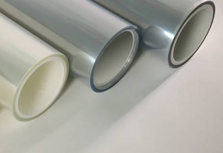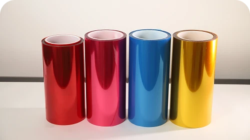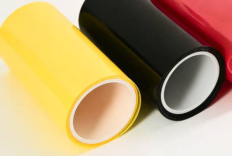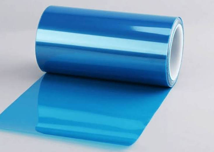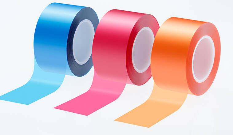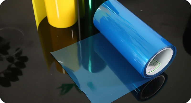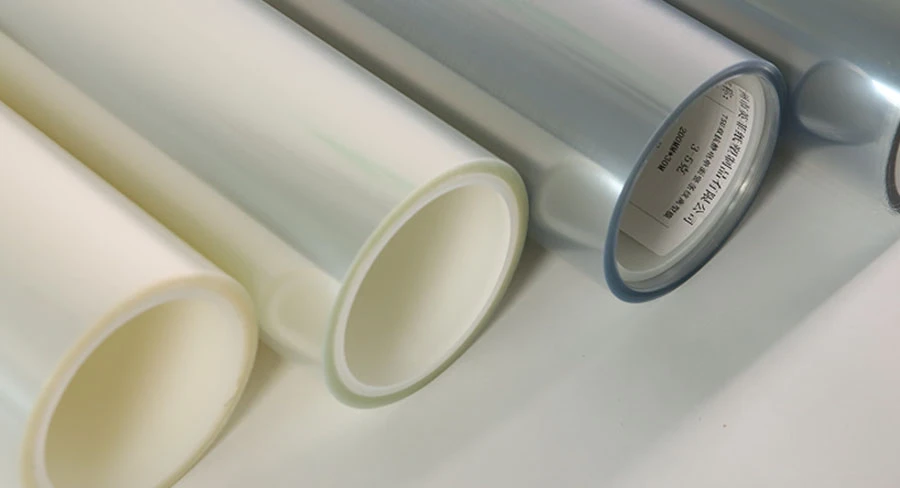
An ultra-light release liner provides a peel force profile below 10 grams per inch (g/in), allowing ultra-thin adhesives, fragile substrates, and optical-grade coatings to release smoothly without distortion or mechanical tearing. While standard liners operate between 15 and 50 g/in, specifying a release force below 10 g/in requires precise balance: the release must remain low enough to protect micro-thin adhesive matrices, yet robust enough to prevent spontaneous separation, web slippage, or air tunneling during rotary converting.
Successfully deploying sub-10 g/in release films requires selecting the right silicone chemistry, evaluating adhesive-liner interaction, and enforcing strict tension and static grounding controls on the production floor. This guide examines the mechanical definitions of ultra-light release forces, identifies critical applications, evaluates the three primary processing risks, and outlines shop-floor handling protocols and technical data sheet (TDS) auditing steps.

Defining “Ultra-Light”: The Physics and Standards of Peel Force Under 10 g/in
In industrial silicone coating terminology, release force measures the resistance required to strip a pressure-sensitive adhesive (PSA) from a coated backing film under standardized test conditions. An ultra-light release classification generally denotes peel values that fall below 10 g/in (approximately 3.8 to 4.0 g/cm or ~0.04 to 0.10 N/25mm).
Because peel values vary with test parameters, absolute force numbers must always specify the test method, pull angle, stripping speed, and reference adhesive tape.
Standard Industrial Classification of Peel Force Profiles
| Classification | Nominal Peel Range | Reference Standard | Typical Chemistry / Substrate |
|---|---|---|---|
| Ultra-Light Release | < 10 g/in (< 0.10 N/25mm) | FTM 1 / ASTM D3330 (180°, 300 mm/min, Tesa 7475 standard) | Platinum-cured addition silicone on optical PET or fine-gauge films |
| Light Release | 10 – 25 g/in (0.10 – 0.25 N/25mm) | FTM 1 / FTM 3 (180° or 90°, 300 mm/min) | Modified solventless silicone on PET or glassine paper |
| Medium / Modified | 30 – 60 g/in (0.30 – 0.60 N/25mm) | FTM 1 (180°, 300 mm/min) | Silicone with controlled-release additives (CRA) |
| Tight / Heavy | > 70 g/in (> 0.70 N/25mm) | FTM 1 / FTM 4 (high-speed delamination assays) | High-CRA silicone formulations for differential dual-liner setups |
Achieving a consistent peel below 10 g/in requires specialized coating technologies:
- High Crosslink Density Addition-Cure Silicones: Thermal-cured solventless or solvent-based systems utilizing platinum catalysts provide a dense, slick polydimethylsiloxane (PDMS) surface network. This architecture minimizes mechanical interlocking with tackified adhesives.
- Absence of Controlled Release Additives (CRA): Formulations intentionally exclude high-friction vinyl resins or silicate additives that formulators use to tighten release values.
- Surface Smoothness of the Base Substrate: Extruded polyester (PET) films offer superior surface uniformity compared to paper backings. Minimal surface roughness ensures the silicone spreads evenly at low coat weights, eliminating local micro-peaks that cause release spikes.
When integrating high-precision carrier films into tight-tolerance manufacturing, reviewing verified release film options helps clarify which base thickness and surface uniformity align with your specific PSA system.
Critical Industrial Applications That Demand Sub-10 g/in Peel Profiles
Sub-10 g/in liners are rarely deployed in general industrial packaging or rugged label stocks because the bond is too weak to retain heavy adhesive layers through aggressive shipping or rough handling. Instead, ultra-light release films serve high-precision manufacturing where mechanical resistance during liner removal damages the functional component.
Application Suitability Matrix: Ultra-Light Release Film
| Application Sector | Mated Adhesive / Substrate | Functional Driver for < 10 g/in | Typical Failure if Peel Exceeds Target |
|---|---|---|---|
| Optically Clear Adhesives (OCA) for Displays | Ultra-thin acrylic gel layers (25 μm to 100 μm) | Prevents optical haze, stress whitening, and shear deformation | Micro-voids, optical distortion, or adhesive web stretching |
| Semiconductor & Wafer Dicing Tapes | UV-curable acrylic or synthetic rubber matrices | Ensures clean, zero-strain removal after fragile wafer backgrinding | Die fly-off, substrate micro-cracks, or premature mechanical lifting |
| Micro-Gasket & Porous Foam Die-Cutting | Open-cell polyurethane, silicones, or conductive foams | Protects fragile foam walls from cohesive rupture during weeding | Structural foam tearing or cell-wall delamination during matrix stripping |
| Flexible Printed Circuits (FPC) Bonding Sheets | Unsupported ultra-thin transfer adhesives (< 15 μm) | Allows automated high-speed peel without warping polyimide traces | Trace delamination or substrate buckling under separation tension |
Optically Clear Adhesives (OCA) and Display Films
Modern multi-layer touch panels, OLED displays, and automotive instrument clusters use liquid or film-based OCAs that must remain flat and transparent. If an OCA release liner requires 20 g/in to strip, the peel tension pulls the soft, elastomeric acrylic layer, causing optical distortion or thickness variations. An ultra-light liner allows automated equipment to strip the carrier cleanly without stretching the adhesive.
Porous Foams, Aerogels, and Conductive Gaskets
Materials like open-cell microcellular polyurethane foams, thin silicone sponges, and metallized conductive fabrics have low internal tensile strength. During converting, if the release force exceeds the foam’s internal cohesion, the matrix tears apart before releasing from the liner. Sub-10 g/in liners prevent cohesive foam rupture during high-speed matrix stripping.
Ultra-Thin Adhesive Transfer Films
Free-standing adhesive films without structural carriers (such as scrims, tissues, or PET cores) deform when pulled. Sub-10 g/in liners protect adhesive films as thin as 5 to 12 microns, ensuring the material transfers smoothly onto target components like flex circuits, optical sensors, or wearable devices.
The 3 Core Operational Pitfalls of Ultra-Light Release Liners
Ultra-light release liners introduce distinct manufacturing challenges. Because the silicone-to-adhesive bond is minimal, standard converting assumptions no longer apply.
Operational Failure Modes, Root Causes, and Countermeasures
| Failure Mode | Underlying Mechanism | Operational Risk | Engineering Countermeasure |
|---|---|---|---|
| 1. Premature Delamination & “Flying Parts” | Insufficient shear/tack holding power along high-speed curved paths | Die-cut parts fly off rotary dies; web wraps around idle rollers | Lower web tension before the die; use vacuum-assisted transport conveyors |
| 2. Post-Cure Peel Aging Drift & Lock-Up | Unreacted siloxane oligomers or environmental cross-linking | Peel force drifts from 6 g/in up to 25+ g/in over shipping/storage | Require ≥ 90% Subsequent Adhesion (ROA); test accelerated aging (70°C) |
| 3. High Static Attraction & Contamination Scavenge | Triboelectric charge build-up on non-conductive polyester film | Liners snap back to metal parts; airborne dust contaminates adhesive | Mount active ionization bars; specify ESD/topical antistatic backing layers |
1. Premature Delamination and Part Ejection
When a web travels through a rotary die-cutter at 30 to 80 meters per minute, it bends across idler rollers, turning bars, and anvil stations. Centrifugal force and web tension cause sub-10 g/in liners to separate spontaneously from converted parts. Small die-cut parts lift off the liner (“flying parts”), foul the die station, or wrap around pull rollers, causing line stops.
2. Peel Aging Drift and Adhesive Lock-Up
A liner that measures 6 g/in at the coating facility can change over time. If the silicone coating contains unreacted crosslinkers or catalyst residues, the silicone layer continues reacting during long-term ocean shipping or warm storage. Alternatively, small-molecule silicone fluid migrates into the adhesive matrix, or tacky acrylic resins wet out deeper into micro-fissures in the silicone layer. As a result, a 6 g/in specification can drift to 18–25 g/in after 90 days. This causes automated pick-and-place feeders to jam or pull the adhesive away from its target substrate.
3. Static Buildup and Contamination Attraction
Ultra-light release films separate with minimal mechanical resistance, but rapid separation generates high triboelectric charges on non-conductive PET surfaces. Without sufficient adhesion to hold the layers flat, static charges cause the stripped film to snap back against equipment, stick to machine frames, or attract airborne dust. In cleanroom assembly, this particulate attraction ruins optical layers and causes electrical shorts in microelectronics.
Workshop Handling Rules: Tension, Static, and Atmospheric Control
Converting facilities cannot run sub-10 g/in release liners using the same machine setups applied to paper liners or standard 30 g/in films. Stable processing requires precise adjustments across tension control, ionization, and climate management.
Recommended Workshop Setup for Ultra-Light Liners

[Unwind Station]          [Rotary Die / Kiss-Cut]         [Matrix Stripping]
+--------------+          +--------------------+          +----------------+
| Closed-Loop  | -------> | Low-Radius Anvil   | -------> | Minimal Angle  |
| Dancer-Arm   |          | Zero Shear Slip    |          | Peel Wedge     |
| Low Tension  |          +--------------------+          +----------------+
+--------------+                    |                             |
|                            v                             v
[Active Static Bar]        [Ionizing Blower]              [Active Static Bar]
Target: < 0.5 kV           Target: < 0.2 kV               Target: < 0.5 kV
1. Web Tension and Roller Geometry Rules
- Maintain Low, Closed-Loop Web Tension: Set unwind and rewind tension to the lowest stable threshold—typically 15% to 30% below settings used for standard liners. High web tension stretches the carrier film elastically; when that tension releases, the elastic snap-back shears the adhesive off the liner, causing tunneling.
- Avoid Small-Radius Idler Rollers: Route the web over rollers with the largest practical diameter (preferably ≥ 75 mm to 100 mm). Passing an ultra-light liner around sharp turning bars or small idler pins introduces severe bend radii that force the outer laminate layer to peel away from the liner.
- Keep Web Paths Supported: Prevent unsupported web spans longer than 500 mm. Use vacuum transport belts or driven nip rolls to prevent floating and flutter during high-speed runs.
2. Static Neutralization Protocols
- Install Active Ionization Bars at Separation Zones: Mount static-elimination bars directly over the unwind zone, immediately before and after the die-cutting station, and at the final rewinding nip.
- Keep Residual Voltage Under 0.5 kV: Monitor web surface charge with a handheld field meter. Static charges exceeding 2.0 kV cause film clinging and particulate contamination.
- Specify Antistatic (ESD) Liners When Feasible: For cleanroom converting or automated SMT placement, use release films treated with an antistatic backing layer (surface resistivity of 108 to 10^{10} Ω/sq). This prevents charge accumulation regardless of ambient line speeds.
3. Atmospheric and Climate Management
- Control Ambient Storage Conditions: Store rolls between 18°C and 24°C with a relative humidity (RH) of 45% to 55%. Avoid storing rolls near overhead heat sources, exterior warehouse doors, or direct sunlight.
- Allow 24-to-48-Hour Acclimatization: Bring rolls into the cleanroom or converting bay in their protective plastic wrapping at least 24 hours before slitting or converting. If cold film meets a warm, humid production room, moisture condenses on the silicone surface, causing adhesion variations and slippage.
Engineering Procurement Framework: How to Audit a < 10 g/in Release Liner TDS
Technical Data Sheets (TDS) for ultra-light liners can be misleading if they report only a single nominal release value. Sourcing teams and process engineers should evaluate four technical parameters before qualifying a production roll:
TDS Parameter Audit Checklist for Sub-10 g/in Release Films
| Critical TDS Metric | Target Specification Range | Verification Test Method |
|---|---|---|
| 1. Baseline Peel Value & Tolerance Band | Target mean ± 1.5 to 2.0 g/in across both MD and CD directions | FTM 1 (180°, 300 mm/min, with specified reference tape) |
| 2. Subsequent Adhesion Ratio (ROA / SAS) | ≥ 90% (≥ 95% preferred for optical electronic grades) | FTM 11 or ASTM D3330 (Subsequent Adhesion to Steel) |
| 3. Silicone Extractable Oligomers (Migration) | Minimum curing degree ≥ 95%; residual silicone < 10 mg/m² | Solvent extraction (MIBK / Heptane) followed by FTIR or Atomic Absorption |
| 4. Thermal Stability Under Heat Aging | Delta peel force < 20% after thermal soak (e.g., 70°C for 72 hours) | Accelerated Aging Test (Finat FTM 1 after heat cycle) |
1. Release Force Tolerance Band (Cross-Direction & Machine-Direction)
A TDS that advertises “5 g/in” must clarify the tolerance range. On a wide roll (e.g., 1,300 mm), uneven coating can cause the edge to measure 4 g/in while the center measures 11 g/in. For critical processes, confirm that the supplier tests cross-direction (CD) and machine-direction (MD) profiles, maintaining a tolerance band within \pm 1.5 to 2.0 g/in of target.
2. Subsequent Adhesion Ratio (ROA / SAS)
The Subsequent Adhesion Ratio (or Residual Adhesion) indicates how cleanly the silicone cures. When standard testing tape is removed from the release liner and applied to a clean stainless-steel panel, its remaining adhesive strength is measured against a control tape. A score below 90% indicates that uncured silicone molecules or free oligomers have migrated into the adhesive. This residual silicone ruins the adhesive’s bonding capacity on its final target surface. For electronics, optical bonding, and medical manufacturing, demand a verified ROA of ≥ 90% (or ≥ 95%).
3. Silicone Migration and Extractables Testing
Free siloxanes can ruin downstream processes like soldering, wire bonding, painting, or optical lamination. Confirm that the supplier validates cure completion using solvent extraction (e.g., extracting unreacted components with methyl isobutyl ketone or heptane, followed by FTIR or atomic absorption spectroscopy) to keep extractable silicone levels within acceptable engineering limits.
4. Thermal Aging Delta
Because chemical reaction rates rise with temperature, confirm the supplier’s thermal aging stability data. Standard validation measures peel values before and after conditioning at elevated temperatures (typically 70°C for 72 hours under pressure). If the post-aging peel force doubles from 6 g/in to 14 g/in, your converting line will face delamination problems after shipping or warm warehousing.
Key Takeaways
- Strict Boundary Definition: An ultra-light release liner provides an ultra-low peel force below 10 g/in (< 0.10 N/25mm). This is typically achieved using platinum-cured addition-cure silicones applied to ultra-smooth PET base films without controlled-release additives.
- Application Drivers: These liners protect delicate adhesives like optical clear adhesives (OCA), fragile open-cell foams, and unsupported transfer films, preventing stretching, stress-whitening, and cohesive structural tears.
- Three Processing Hazards: Low adhesive grip increases the risk of premature part ejection during converting, peel-force drift from thermal aging, and high triboelectric static charges that attract dust in cleanroom environments.
- Line Handling Adjustments: Running sub-10 g/in films requires reducing web tension by 15% to 30%, using large-radius idler rollers to prevent buckling, and installing active static-neutralization bars at all unwind and rewinding points.
- Procurement Audits: Never qualify an ultra-light liner on baseline peel force alone. Require verification of subsequent adhesion ratios (≥ 90%), cross-web coating consistency, minimal extractable siloxanes, and stable peel profiles after thermal aging.
Frequently Asked Questions (FAQ)
Can ultra-light release liners be paired with high-tack acrylic adhesives?
Yes, high-tack acrylic adhesives can be paired with sub-10 g/in release liners, but this combination requires testing. High-tack acrylic formulations wet out aggressively across surfaces. Over time, the adhesive can conform tightly to the silicone layer, causing peel force to climb above target levels during storage. When pairing high-tack adhesives with sub-10 g/in liners, run accelerated aging tests (typically 70°C for 72 hours under 5 kg load) to confirm the release value stays within acceptable processing limits.
How does transit temperature affect sub-10 g/in release liners?
Uncontrolled shipping temperatures accelerate chemical interactions between adhesives and silicone layers. In overseas shipping containers, internal temperatures can exceed 55°C to 60°C. This heat can cause unreacted silicone oligomers to cross-link or allow adhesive resins to flow deeper into the silicone coating, causing peel values to drift upward. To prevent release lock-up, specify fully cured silicone chemistries, evaluate high-heat aging data, and ship materials in climate-controlled containers when traversing hot shipping routes.
What is the typical shelf life of an ultra-light release film?
Under controlled storage conditions (18°C to 24°C and 45% to 55% RH), an ultra-light release film typically retains its specifications for 6 to 12 months. However, because sub-10 g/in release profiles have narrow operating windows, re-test peel values and subsequent adhesion ratios before feeding rolls that have been stored for more than six months into high-precision production lines.
Why do converted parts fly off the liner on rotary die-cutting lines?
Parts eject from ultra-light liners when the mechanical shear and peel forces generated by the web run exceed the liner’s adhesive holding strength. This problem occurs when the web moves around small-radius idler rollers, flexes over sharp angles, or runs under excessive web tension. To stop part ejection, lower web tension, route the material over larger-diameter rollers, reduce line speeds, and add vacuum-assist belts to support cut parts after the die station.