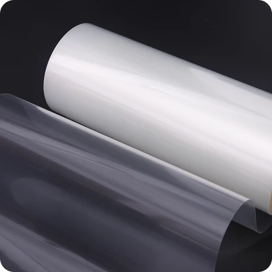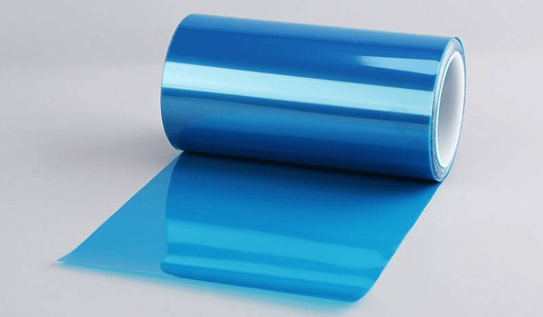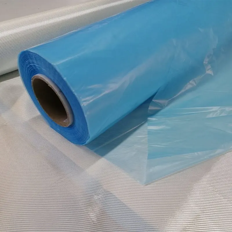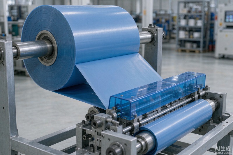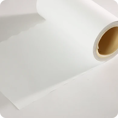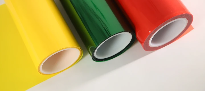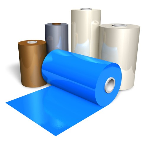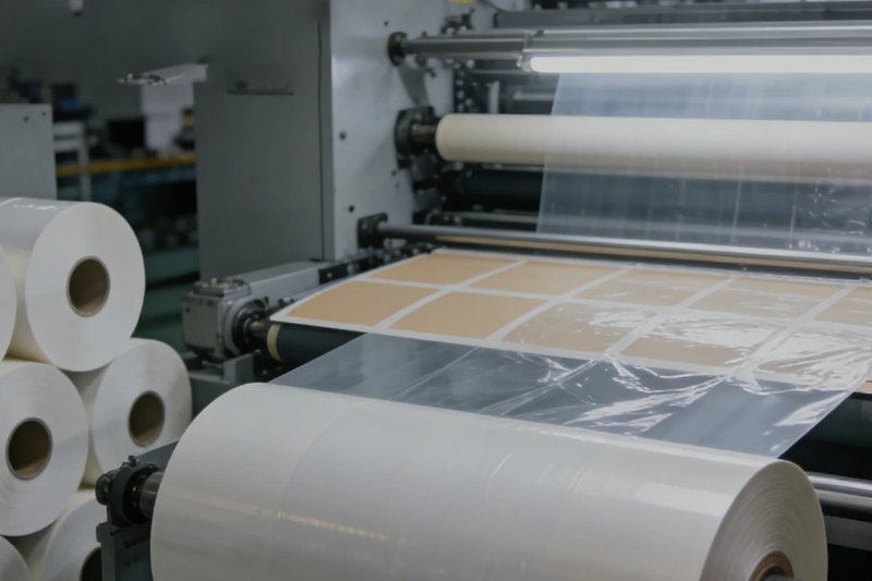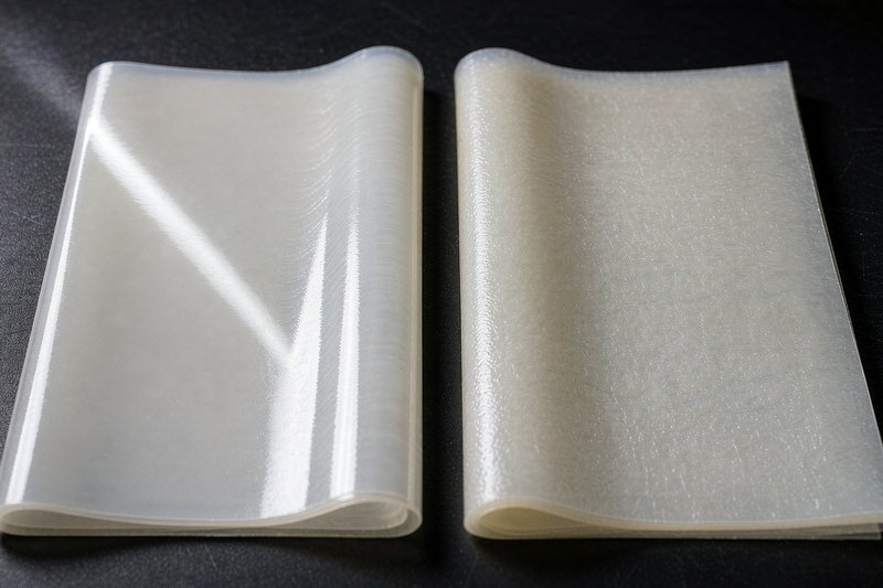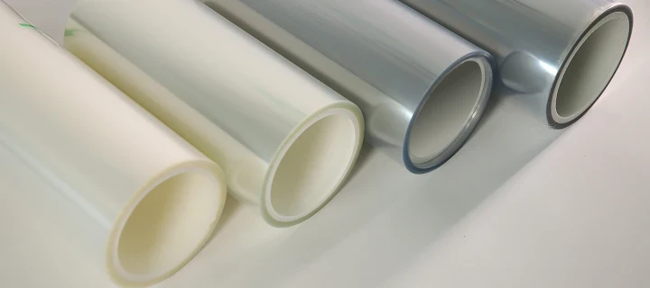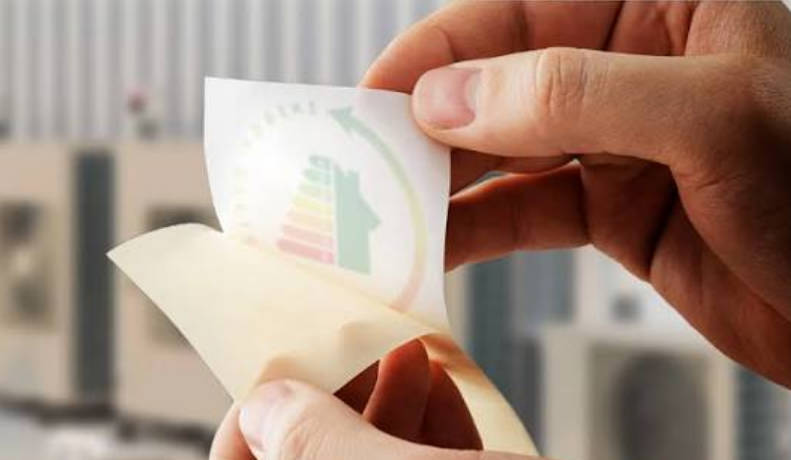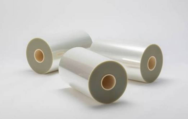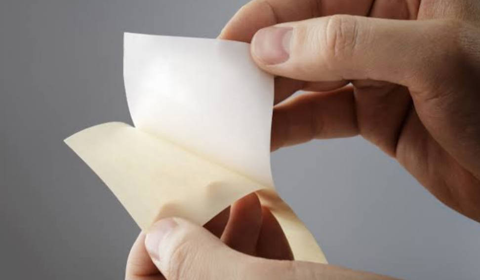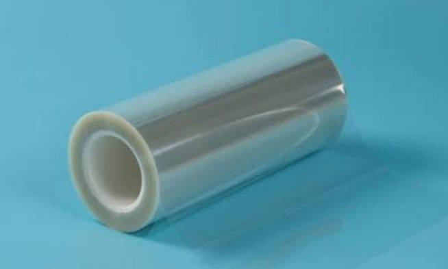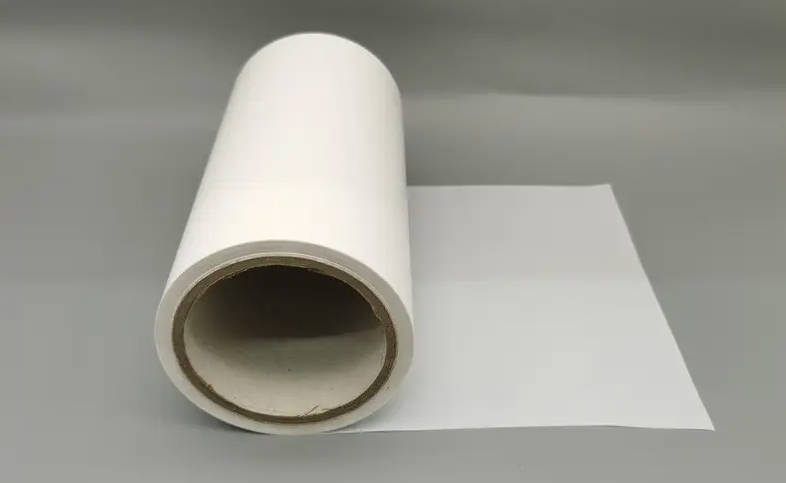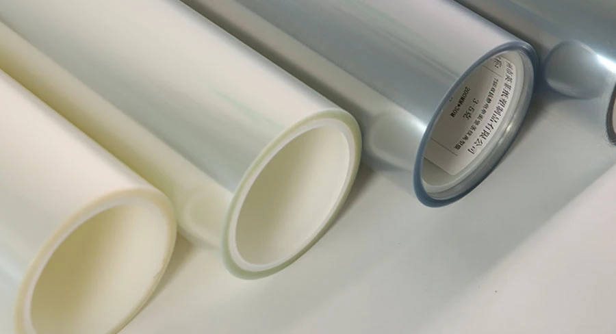
PET release film serves as a critical carrier and temporary backing that protects sensitive adhesive surfaces, facilitates clean transfer, and preserves tack performance until final bonding. Selecting the correct release liner requires matching three technical variables: the substrates mechanical properties, the chemical compatibility between the release coating and the adhesive mass, and the target release force profile under dynamic converting conditions.
Mismatched release chemistry can cause catastrophic adhesive passivation, silicone transfer, web tears during high-speed kiss-cutting, or delamination in storage. This guide examines the structural composition of biaxially oriented polyester liners, breaks down the chemistry of crosslinked silicone, fluorosilicone, and non-silicone coatings, establishes quantitative release force metrics, and provides an engineering framework to specify liners for precision die-cutting, electronic components, and composite fabrication.
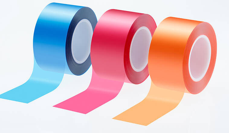
Understanding PET Release Film: Substrate Anatomy and Key Performance Drivers
A polyethylene terephthalate (PET) release film is a multi-layer composite consisting of a biaxially oriented polyester core film, an optional surface treatment or chemical primer, and a cured release coating. In precision converting, engineered PET release film provides distinct mechanical advantages over paper-based alternatives such as glassine, clay-coated kraft (CCK), and polycoated kraft (PCK).
Typical Cross-Sectional Structure of Engineered PET Release Film
| Top Layer | Functional Release Coating | Controls interfacial peel tension; crosslinked Polydimethylsiloxane (PDMS), Fluorosilicone, or Non-Silicone (Alkyd / Acrylic). |
| Interlayer (Optional) | Functional Primer / Pretreatment | Chemical adhesion primer, in-line corona treatment, or transparent conductive antistatic (ESD) layer to prevent silicone rub-off. |
| Core Layer | BOPET Base Substrate | Biaxially Oriented Polyethylene Terephthalate core providing dimensional stability, tensile modulus, and high optical clarity. |
| Backside Layer | Secondary Functional Surface | Bare PET, permanent dissipative anti-static coating, or secondary differential release layer (for dual-sided self-wound tapes). |
Key Substrate Properties
Dimensional Stability: The biaxial stretching process (MD and TD orientation) provides low elongation under machine tension, preventing dimensional distortion during high-tension roll-to-roll slitting.
Caliper Uniformity: Polyester films exhibit tight gauge tolerance across wide web formats, making them suitable for kiss-cutting where tool penetration must stop within fractions of a micron from the carrier face.
Thermal Resistance: Unlike standard polyolefin films (PE or PP), standard PET maintains structural integrity through thermal curing tunnels up to 150°C, depending on dwell time and tension control.
Surface Smoothness and Cleanliness: With minimal surface roughness and virtually zero fiber particulate shedding, PET liners are compatible with optical-grade pressure-sensitive adhesives (PSAs) and cleanroom casting processes where micro-voids or surface telegraphing degrade optical clarity.
Coating Chemistry Decoded: Silicone, Fluorosilicone, and Non-Silicone Formulations
The primary function of a release coating is to lower the solid surface energy of the substrate below the surface tension of the contacting adhesive layer. This mismatch creates an interface with low work of adhesion. Specifying the coating chemistry requires analyzing both the cure mechanism and the chemical family of the target adhesive.
Coating Chemistry Selection Framework
| Crosslinked Polydimethylsiloxane (PDMS) | Solventless or solvent-based thermal hydrosilylation cure with platinum catalyst | Broad release range, economical standard, high residual tack retention (>90%) | Standard acrylics, hot-melt rubbers, polyurethanes, epoxies |
| Fluorosilicone Formulations | Fluorocarbon-modified siloxane backbones | Prevents siloxane-to-siloxane chemical co-curing, maintains stable boundary release | Mandatory for pure silicone PSAs, silicone gels, thermal pads |
| Non-Silicone Formulations | Pure crosslinked acrylics, modified alkyds, polyolefins, or fluoropolymers | Zero extractable silicone migration, cleanroom compliant, higher release force range | Semiconductor dicing, FPCB coverlay pressing, optical and automotive paint lines |
Solvent-Free vs. Solvent-Based Thermal Cure Systems
Most commercial silicone release layers rely on addition-cure (hydrosilylation) chemistry, where vinyl-functional polydimethylsiloxane (PDMS) reacts with silicon hydride (Si-H) crosslinkers in the presence of a platinum catalyst.
Solventless Silicone Systems: These 100% solids formulations crosslink rapidly under heat without volatile organic compound (VOC) emissions. They provide cost efficiency and high coating speeds on industrial coaters. However, web wetting on ultra-smooth polyester cores can be challenging, requiring precise corona treatment or primer layers to prevent silicone rub-off under mechanical shear.
Solvent-Based Silicone Systems: Curing involves dissolving high-molecular-weight polymers into organic solvents (such as toluene or heptane) before slot-die or reverse gravure application. When the solvent evaporates in the drying oven, it leaves a dense, uniform, thin polymer network. Solvent-based systems achieve superior flatness, high subsequent adhesion strength (residual tack exceeding 90–95%), and low release variation across wide webs.
Fluorosilicone Release Liners for Silicone Adhesives
Standard polydimethylsiloxane coatings fail when paired with silicone-based pressure-sensitive adhesives. Because the chemical structures are similar, the silicone adhesive and silicone release coating co-cure or interdiffuse across the boundary layer, permanently welding them together.
Fluorosilicone release liners solve this problem by incorporating fluorocarbon groups into the siloxane backbone. The fluorocarbon moieties lower the surface energy beyond standard silicone levels and provide steric hindrance against siloxane bonding. When working with pure silicone gels, high-temperature silicone splicing tapes, or thermally conductive silicone pads, fluorosilicone liners are necessary to achieve consistent, repeatable release.
Non-Silicone Formulations: Preventing Contamination
In microelectronics manufacturing, semiconductor packaging, and automotive refinish applications, airborne volatile siloxanes or trace silicone migration can cause catastrophic failures. Trace silicone transfer can poison solder joints, cause pinholing and cratering in subsequent paint coats, or disrupt electrical contacts in relay assemblies.
Non-silicone release films utilize specialized chemistries such as crosslinked acrylic polymers, long-chain alkyds, modified polyolefins, or fluoropolymer coatings. While non-silicone options generally exhibit higher release force profiles and narrower release margins than standard PDMS systems, they eliminate cross-contamination risks across sensitive manufacturing lines.
Chemical Formulation Matrix
| Solventless Silicone | Thermal Hydrosilylation | Acrylics, Hot-melts, Synthetic Rubbers | High (88%–95%) | Very Low (when fully cured) | General industrial tapes, logistics labels, standard kiss-cutting |
| Solvent-Based Silicone | Thermal Platinum-Catalyzed | High-tack Acrylics, Polyurethanes, Epoxies | Very High (> 95%) | Minimal | Optically clear adhesives (OCA), graphic overlays, precision electronics |
| Fluorosilicone | Thermal Catalyst Cure | Pure Silicone PSAs, Silicone Hydrogels | High (85%–92%) | Negligible (Fluorinated Siloxane) | Thermal interface pads, silicone masking tapes, medical patches |
| Non-Silicone (Polymer/Alkyd) | Thermal / Electron Beam (EB) | Acrylates, Polyurethane, Epoxy Prepregs | High to Moderate | Zero Silicone Present | Semiconductor dicing, FPCB pressing, automotive paint masking |
Release Force Dynamics and Testing Standards
Release force is the measurement of peel resistance required to separate a standardized flexible adhesive tape from a release liner under specified peel angle, pull speed, and temperature conditions. It is typically expressed in grams per 25 millimeters (g/25mm) or centinewtons per centimeter (cN/cm).
Industry Release Classifications
Industrial release values are categorized into broad functional bands:
- Ultra-Light Release (1 to 5 g/25mm): Used for delicate, low-tack protective films and wide-width automated web transfers where minimal peeling resistance prevents web stretch and wrinkling.
- Light Release (5 to 15 g/25mm): The baseline standard for precision rotary die-cutting of acrylic transfer tapes and foam gaskets. Enables high-speed automated matrix stripping without lifting the cut parts.
- Medium Release (15 to 35 g/25mm): Balances adhesion hold and peeling ease; commonly configured on the second side of double-sided differential liners or applied against aggressive rubber-resin formulations.
- Heavy / Tight Release (35 to 80+ g/25mm): Deliberately engineered for heavy structural adhesive webs, textured foam substrates, and manual hand-peel consumer products to prevent premature separation during handling and transport.
Testing Methodologies and Environmental Factors
Specifying release force without detailing test conditions often causes manufacturing discrepancies. Standard testing methods such as FINAT FTM 1 (480-hour aging under pressure), FTM 3 (low-speed 180° peel), and FTM 4 (high-speed 180° peel) demonstrate that release force is dynamic rather than static.
Standard Release Peel Test Setup (ASTM D3330 / FINAT FTM 3)
| Sample Mount | Rigid flat test plate | Release liner clamped coating side face-up |
| Peel Arm | Calibrated pressure-sensitive adhesive tape (e.g., Tesa 7475) | Stripped back at a continuous 180° angle |
| Load Cell | Calibrated digital force transducer | Measures instantaneous force in grams per 25mm |
| Drive Motion | Motorized crosshead carriage | Controlled test speed (standard baseline at 300 mm/min) |
Peel Speed Dependence: A liner exhibiting 10 g/25mm at an inspection speed of 300 mm/min (standard laboratory peel test) may exhibit 35 g/25mm on a converting press pulling at 60 meters per minute.
Thermal and Aging Stability: Unreacted siloxane oligomers will slowly migrate to the interface over time, softening the release force, while uncrosslinked acrylic tackifiers can drive post-cure adhesion build. Liners must be evaluated after accelerated aging (typically 70°C at 60% RH under a 20 g/cm² ballast plate for 20 hours).
High-Performance Applications: Where Precision PET Release Liners Are Essential
Operating parameters vary significantly across downstream conversion equipment. Industrial converters select silicone and non-silicone release liners engineered around specific conversion parameters.
Target Application Matrix
| Optical OCA & Display Lamination | Class 1000 Cleanroom grade, zero visual haze, zero surface pinholes | 50–75μm Optical BOPET with low-extraction solvent silicone | Avoiding optical impression marks or micro-bubbles in cured displays |
| High-Speed Rotary Kiss-Cutting | Caliper gauge variation <3%, high tensile modulus, anti-static coating | 25–50μm BOPET, chemical primer base, conductive ESD topcoat | Preventing web tears or anvil strikes under high matrix stripping speeds |
| MLCC Ceramic Slurry Wet Casting | High thermal endurance, chemical solvent resistance (MEK/Toluene) | 30–50μm Ultra-Flat BOPET with modified silicone or non-silicone | Preventing slurry dewetting, pinholing, or resin particulate contamination |
| Multilayer Tape & Converting Rolls | Differential release force balance (e.g., 1:3 or 1:4 peel ratio) | Dual-coated differential PET liner with distinct release values per side | Preventing edge delamination or roll blocking during slitting and rewinding |
Optical Displays and Optically Clear Adhesives (OCA)
Lamination of touch screens, polarizers, and automotive OLED panels demands cleanroom-coated optical PET release liners. The coating line must operate within Class 1,000 or Class 100 environments to eliminate airborne lint and micro-particles. Any surface defect in the liner imprints permanently into soft acrylic OCA layers, resulting in refractive optical defects, bubbles, or visual haze once cured.
Precision Die-Cutting and Kiss-Cutting
In high-speed rotary die-cutting, cutting dies penetrate the top face stock and adhesive mass, stopping precisely on the surface of the PET liner without cutting into the base polyester matrix.
Caliper Uniformity: Gauge variations exceeding 3% to 5% across the web profile can cause die strikes to fracture the release liner, causing web breaks on continuous automated packaging lines.
Electrostatic Dissipation (ESD): Fast unrolling and high-speed web movement generate significant electrostatic charges on the non-conductive polyester core. Anti-static treatments (conductive polymeric or metal-oxide coatings yielding surface resistivities between 108 and 1011 Ω/sq) dissipate charges, preventing dust attraction and static shock hazards.
MLCC Ceramic Sheet Casting and Flexible Printed Circuits (FPCB)
In the production of Multi-Layer Ceramic Capacitors (MLCC), a liquid ceramic slurry containing solvents (such as MEK and toluene) is cast directly onto a moving PET carrier film, dried in a tunnel kiln, and stripped.
The liner must exhibit solvent barrier resistance so the liquid slurry does not attack the release layer. It must also have balanced surface tension to prevent slurry dewetting (pinholes) while facilitating clean sheet release without particulate residue. Similarly, in FPCB coverlay pressing, release sheets withstand thermal cycles up to 180°C under hydraulic press pressure without adhering to the polyimide resin.
Troubleshooting Converting Defects: Root Causes and Preventive Actions
When production lines encounter delamination, adhesive residue, or dimensional distortion, issues often trace back to the interface between the release layer and the adhesive. The following diagnostic guide identifies common processing defects and their corrective actions.
| Silicone Migration & Transfer | Loss of subsequent tack when bonding the exposed tape to a target substrate; cloudy film on the adhesive. | Incomplete platinum-catalyzed cure, improper oven profile, or an excessive stoichiometric ratio of unreacted Si-H monomers. | Verify thermal cure temperature; confirm platinum levels; switch to a validated solvent-based coating with >95% residual tack. |
| Zipping Effect (Stick-Slip) | Chattering, jerky peel action accompanied by an audible ripping sound during steady-state unwinding. | Incompatible surface energies causing micro-voiding, non-uniform coating thickness, or inappropriate silicone chain length. | Increase crosslink density; transition to a controlled-release additive (CRA) formulation; lower base pull speed. |
| Liner Tear during Kiss-Cutting | Die blade cuts through or micro-fractures the PET liner, leading to continuous web snaps downweb. | Caliper gauge variation along web width; worn anvil rolls; insufficient tensile modulus in the base film. | Tighten film caliper tolerance; verify anvil gap micrometer settings; upgrade to high-modulus BOPET base substrate. |
| Electrostatic Dust Pickup | Airborne particles cling to the liner face immediately upon unwinding, creating bumps in adhesive transfer. | Surface charge buildup exceeding 5–10 kV due to friction across non-conductive idler rolls. | Install active ionizing bars; apply a reverse-side permanent conductive antistatic (ESD) coating (109 Ω/sq). |
| Premature Pre-delamination | The liner spontaneously detaches from the tape edge or forms blisters inside wound rolls during warehousing. | Release force is too low for the mechanical stiffness (die cut stress) of the face material; thermal expansion mismatch. | Increase release specification (e.g., move from 5g to 15g band); evaluate roll storage winding tension profiles. |
Buyers Specification Framework: How to Define RFQ Parameters for PET Release Film
Procuring custom release liners requires technical alignment between the converter, adhesive formulator, and liner coater. Incomplete specifications often result in processing failures or off-spec sample runs.
| 1. Base Substrate Caliper | Nominal film thickness | 23 μm, 36 μm, 50 μm, 75 μm, 100 μm (Custom calipers on demand) |
| 2. Coating Configuration | Functional face layout | Single-sided, Double-sided identical, Double-sided differential |
| 3. Release Chemistry | Polymer curing system | Solventless PDMS, Solvent-based thermal silicone, Fluorosilicone, Non-silicone |
| 4. Target Adhesive Chemistry | Chemistry of mass to be protected | Emulsion acrylic, Solvent acrylic, Pure silicone, Hot-melt rubber, Polyurethane |
| 5. Nominal Release Target | Specified peel force range | Tight Side: [ ] g/25mm | Easy Side: [ ] g/25mm (Specify test tape & speed) |
| 6. Inline Surface Treatment | Electrical / adhesion prep | Topside ESD, Backside ESD (108–1011 Ω/sq), Primer coat, Corona treat |
| 7. Roll Geometry & Slitting | Precision converting dimensions | Slit width (tolerance ± 0.5 mm), Roll OD, Core ID (3″ / 76mm or 6″ / 152mm) |
Technical RFQ Parameter Specification Checklist
When structuring a request for quote (RFQ) or engaging a manufacturer like YINGFEI for sample validation, supply the following parameters:
- Substrate Thickness & Geometry: Confirm base polyester thickness (typical standard calipers include 23μm, 36μm, 50μm, 75μm, and 100μm) along with custom master or slit roll widths, core diameter (76mm/3-inch vs. 152mm/6-inch), and winding orientation (coating facing inside or outside).
- Coating Configuration: Specify single-sided coating, double-sided identical coating, or double-sided differential coating (with distinct release ratios such as 1:3 or 1:4 to control peeling order in self-wound tapes).
- Specific Adhesive Chemistry: Document whether the liner will contact solvent acrylics, emulsion acrylics, natural/synthetic rubber, hot-melt polyolefins, or silicone adhesives. Providing the exact adhesive designation ensures compatible catalyst and crosslinker pairings.
- Target Release Range: State the target peel force and the verification test method (e.g., FINAT FTM 1 using Tesa 7475 standard acrylic tape, measured in g/25mm at 300 mm/min).
- Special Requirements: Note cleanroom rating limits (e.g., Class 1,000 for optical applications), surface resistivity limits (ESD protection), or strict prohibitions against extractable silicones in clean assembly areas.
Frequently Asked Questions (FAQ)
What is the typical shelf life of silicone-coated PET release film?
Under standard warehousing conditions (20°C to 25°C and 45% to 60% relative humidity, out of direct sunlight), the functional shelf life ranges from 6 to 12 months. Over prolonged storage, exposure to elevated temperatures can cause residual crosslinking reactions or migratory silicone aging, which may alter nominal release force values.
Can silicone-coated PET release film be recycled after industrial die-cutting?
Yes, PET release film is chemically recyclable; however, the crosslinked silicone coating introduces processing challenges into standard mechanical recycling streams. Specialized post-industrial recyclers use solvent stripping or thermal chemical recycling (glycolysis/methanolysis) to separate the silicone network from the underlying polyester matrix, recovering recycled PET (rPET) resin without loss of physical properties.
What is the difference between inline and offline coating of PET release liners?
Inline coating occurs directly on the primary film production line during the film orientation process, typically applying water-based primers, antistatic agents, or light coatings before the film is stretched in the transverse direction. Offline coating applies performance silicones, fluorosilicones, or non-silicone systems using dedicated precision coaters (such as reverse gravure, comma, or slot-die) on fully stabilized, master-roll BOPET. Offline coating offers greater versatility for custom release adjustments and high-specification industrial applications.
How do temperature variations affect dynamic release performance during lamination?
High processing temperatures lower the modulus of pressure-sensitive adhesives, increasing their flow and contact area against the liner coating. This can artificially elevate release force (adhesion buildup). Conversely, extreme cold can embrittle rubber-based adhesives, inducing stick-slip and zipping effects during high-speed unwinding.
Key Takeaways
Core Substrate Advantages: Biaxially oriented PET provides superior caliper uniformity, dimensional stability under web tension, and higher thermal resistance than paper release liners, making it the benchmark carrier for precision kiss-cutting and optical conversion.
Coating Chemistry Dictates Function: Standard solventless or solvent-based silicone covers acrylic and rubber adhesives; fluorosilicone is chemically required for silicone-based adhesives; and non-silicone formulations are essential to prevent silicone contamination in semiconductor, medical, and automotive paint environments.
Release Force is Dynamic: Release force depends on peel speed, peel angle, test tape chemistry, and aging conditions. Specifying performance requires defining standard test protocols (e.g., FINAT FTM 1 / FTM 3) alongside dynamic processing speeds.
Root Causes for Processing Defects: Failures such as silicone transfer, zipping, and web tears stem from incomplete curing, surface energy mismatches, electrostatic accumulation, or loose caliper tolerances. These can be resolved by optimizing chemical formulation and web tension controls.